Forum Replies Created
- AuthorPosts
-
Hi,
the Toshiba TC4013BP will work fine to replace the HEF4013BP.
Greetings RaMaBo
Hi trackbeo,
it works here for me fine:

Maybe hit ‘Reload’ in your browser.
Greetings from Munich
Hi
This combination fits into also in the Beovision 8/40 (MK I and MK II) 😉
Hi,
try any of the audio sources on the BEO4 and then in front of the Beolab 3500 press
19 June 2023 at 11:29 in reply to: BeoCenter 2300: where is the motion sensor for the doors located? #47231No, there are two identical IR transceivers on each side, both in the yellow circles.
The IR sensor is in the small hole right of the notch (on the left side sensors)Hi,
the Beolink active (1636) has a different connetion option than the older Beolink active (1616).
The older has two powerlink connections which should work flawlessly with a MK3 powerlink cable.
The newer Beolink active (1636) has one connection as PC (to the computer) and _one_ powerlink connector.May be the BeoLab 7.4 is connected to the wrong socket? It should be connected to the powerlink socket.
19 June 2023 at 10:41 in reply to: BeoCenter 2300: where is the motion sensor for the doors located? #47229Hi,
the LED in the inwards pointing notch is an IR LED sending invisible light towards the center of the system, but nothing will be reflected to the IR sensor. Except if you move your hand in the IR light area. Then a reflection could be detected 😉 and the doors will be opened.
Hi Peter,
sorry i don’t have a photo available but it should be clear when you read the following post from the old forum: Old Post
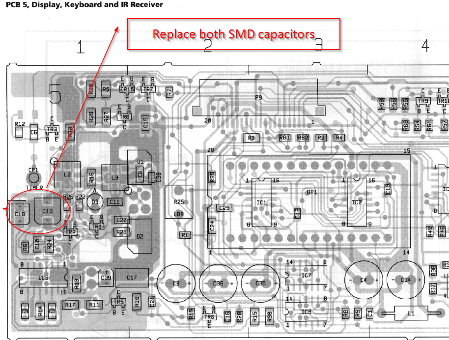
There are two small silver cylinders just near the U2506 integrated circuit. Best replace both because they are old and make problems.
To get the best access to them the cover is unmounted. You also have to unsolder the red LED, the IR receiver diodes and the Light dependant resistor before.
I hope this helps
Ralph-Marcus
Hi,
in the archived forum2 you can read a lot about the IR receiver problems and how to solve them. Mostly it’s about two SMD capacitors near the U2506 integrated circuit that need to be excanged. 🙂
I once replaced them in a Beolab 3500: Here
And here is a short description of how to replace the capacitors.
Hi,
there’s a quite detailed description in the archived forum:
https://archivedforum2.beoworld.ouronlineserver.com/forums/p/16661/180655.aspx#180655But read the whole thread too.
Hi,
i don’t know much about that stuff you described, but maybe a picture of the original B&O Bassreflex conversion kit might help you 🙂
https://archivedforum.beoworld.org/forums/p/16202/124895.aspx#124895
Lots of people were more than happy when the Redline 60.2 (or converted Redline 60) played their music.
Hi,
the components that make headache are not so critical:
80µF / 25 V could be replaced with 100µF /25 V
33µF / 64V could be replaced with 47µF / 63V
1,6µF /25V could be replaced with 2,2µF / 25V or to be as near with a 4,7µ / 25V in series with a 2,2µF /25 V resulting in 1,5 µF /25V but not really necessary.
125µF / 16V could be replaced with 100µF /16 V or to be as close as possible get a 100µF /16V with a parallel 22µF /16V
The 80µF and 33µF are used to ‘clean’ the supply and bias voltages.
The 1,6 µF is for removing the DC offset from the input and output so i would use just a simple 2,2µF. It has no influence to the frequency response of the RIAA preamp.
Also every capacitor for 64V could be replaced with a 63V typeI hope this helps 🙂
Hi,
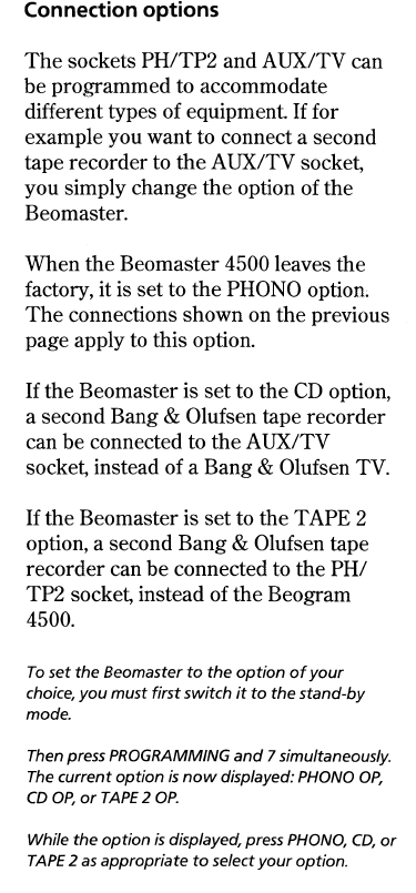
could be that the Beomaster 4500 is set to another option programming.

Maybe this helps 🙂
Hi,
the User name you should provide is: BM-User.
The complete process could be found here:
https://archivedforum2.beoworld.ouronlineserver.com/forums/p/20471/168849.aspx#168849
Not your posting but one i found in the old forum.
Hi,
the repair of the IR Board is indeed simple 🙂
Replace the two silver SMD caps. If the space allows you can replace them with ordinary electrolyctic capacitors ( 22µF / 6.3Volt ). To remove the old capacitors hold the PCB and with twist each capacitor with a plier. This way the cap will be removed from its base without tearing the traces. Now remove the two pins soldered to the PCB and clean the board with IPA and solder the new caps to the board. Mind the polarity!!!Hi,
the Core could be connected to the Beolab 7.2 with a power cable with the matching connectors ( two C7 plugs ). It’s the same way the Beovison 7 is connected to power, except you use a Core instead of the TV 😉
Hi,
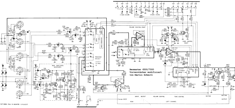
i attached the image i once loaded, but the quality of the circuit diagram is not so good 🙁
But it should be usable. Maybe “Die Bogner” can resend the image in a better quality.

- AuthorPosts
