Forum Replies Created
- AuthorPosts
-
Great to hear you worked it out ?
When you are going to replace it a piece of advise is to also disconnect the power for the Beosystem 4500 to avoid any risk of damage anything in the process
I noticed that Quality Dream Audio is out of stock on the one I have, but they have this one that I’ve attached. Would this work with my system? The only difference I see is the extra port for TV on it whereas the one I have only has the 3 ports, one being marked TV, which is the one that I use to relay from the bluetooth adapter to run my TV in the room above. Please let me know. I appreciate all your help with this, very frustrating.
Yes this would work the same. The extra port for TV is just an antenna cable pass through that was left out in the later versions of the MCL2AV.
2020 is the one with the Antenna port.
The other ones are without. The differences lies in which setup type the where bought for and if the had the IR eye or not. For your setup it should not matter
I would not suspect anything else at this point.
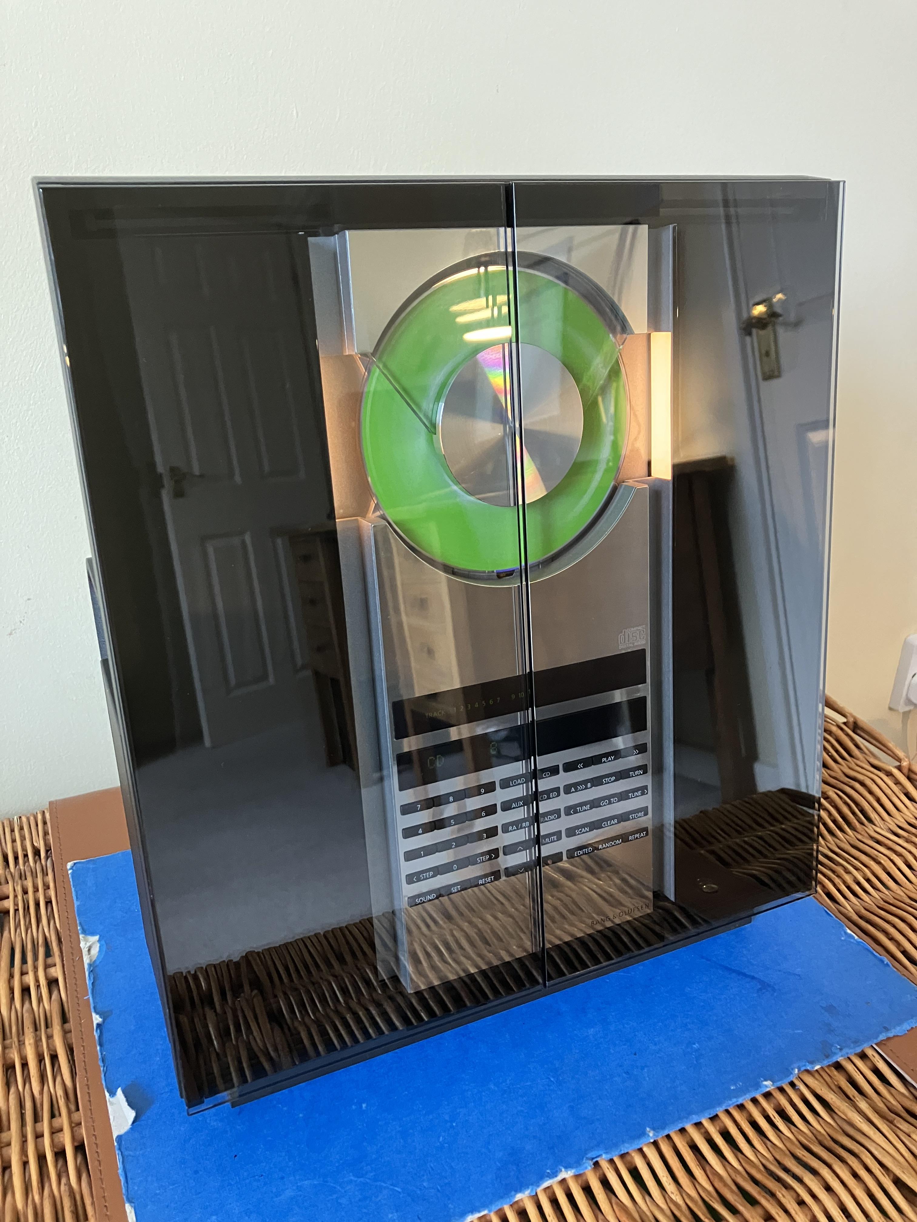
Lovely Beocave!
Thanks ? though it is allready reorganised since the picture was taken to make space for more items ?
I’ll also look into which capacitors I need to replace first for laser.
Unless you have good experience with mounting SMD caps I will recommend the Approach Guy have in the linked thread where he use standard capacitors instead. In my experience the SMD ones are not easy to solder on to the board with a soldering iron
Quick photo of display with contrast too high (do I mean too low?) – only BBC R2, RADIO A and STEREO should be visible! It is much better viewed direct on, rather than at an angle.
Very good illustration of how it should not be 🙂
I am now able to check my display in the dark and it is far too bright! (the non-lit ‘pixels’ are glowing too much which reduces clarity). I’ll re-adjust tomorrow, probably back to where I started. It’s a bit of a faff to adjust so I actually wish I’d never attempted. So if you can live with yours as it is then I recommend doing nothing!
Good to know. I have not noticed any issuses with brighness on my Ouverture, but if I do at one point I might have to consider what I can live with.
On a positive note, I replaced both belts today – first time I have tried that and it was a bit tricky but successful.
Yes they are tricky. When I did it I ended up re wirering the doors as I probably had disassembled the mechanism to much. But with the extra lenght there was in the existing belts I have no doubt that belt change is mandatory.
I also replaced the lithium battery – I (carefully) soldered a new battery directly rather than use a socket because the sockets I bought were a bit large and may have pushed against the upper shielding
Also good to know in order to get the right battery from the start.
Given that this is the first battery change in 20+ years I reckon that the replacement will probably outlive me. (Old battery measured 2.86V no load, new one was 3.2V).
And based on that, you are right, that next battery replacement is probably not worth thinking on.
Apologies for hijacking madskp’s thread for the non-CD-related activities but I wish him all success in getting his Ouverture fully functional.
No need to apologise. Allways great with extra inputs, especially since my Ouverture is still open. I would hate to find out that I should have done this little extra thing when I had just reassembled the whole thing 😉
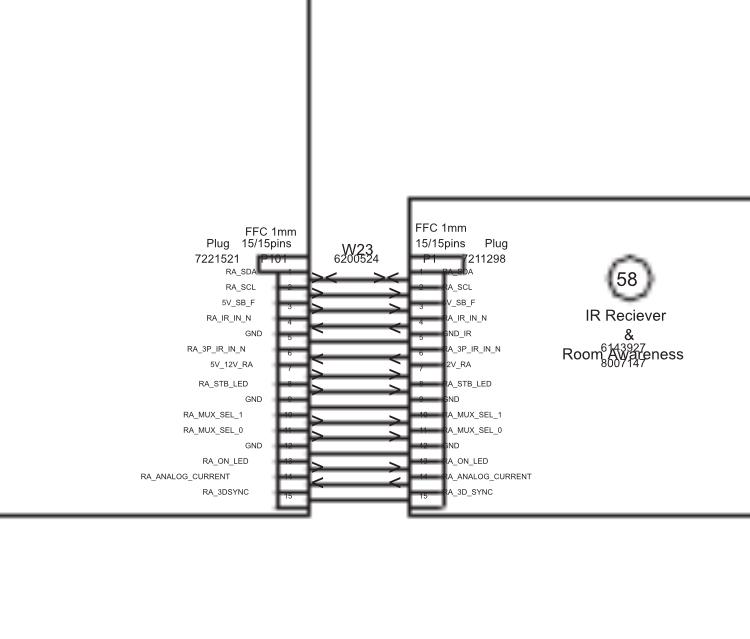
And BTW pin 5 is also ground so if you touch that while measuring you will probably also get 0V. Those small pins in these connectors are usually fididly to measure on
Depending on how easy it is to see the pin numbers direction it could be that you are counting the pins from the wrong direction?
Counting to pin 4 from the wrong direction seems to be a ground pin which will read 0V

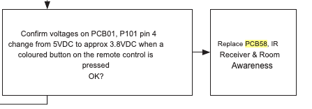
This test is only for checking if 5V drop to 3.8V, so I would expect a 5V reading.But the could be problems before in the chain. Try to look at page 3.4 in the servicemanual. There is a flowchart with things to test where this is only part of it.
The TV has to be connected to mains for the test, and all internal connections be intact, but as its part of a test for tv not turning on that should be it.
I tried with the mains plugged in and when I touched the pin with the multimeter something on the awareness board blew up
Sorry to hear that. Can you tell which component that blew up based on your pictures?
at this point I dont even know if it’s worth fixing this tv. Was the problem something else on the video engine and now that I made that part blow up would it affect the video engine in case it was okay and the problem was really the awareness one?
Hard to tell, but at least when you get the new PCB you will know if that was it or if it is the video engine part
wauw. Great looking. Just need some speakers now
but the red lights are on the speakers as we speak, even though the MCL2AV box is not plugged in currently.
The speakers are active speakers with built in power supplies, so they will always be in standby indicated by the red light if they are plugged into mains even though there is no source.
Assuming they are wired to the main system in the living room and the MCL2AV box is just an addition to let you run them with the IR eye and remote for additional sound in another room.
I would assume that yes. That is the way his system was intended to be used, as a link room to the main system.
The IR eye, when the MCL2AV box is plugged in, does not come on, as the red light does not even light up.
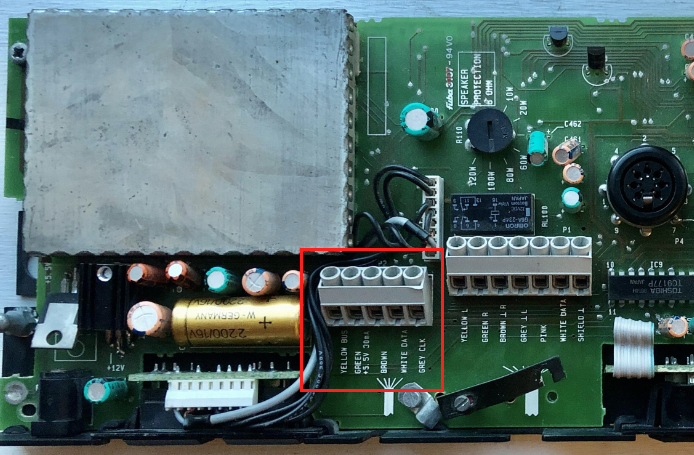
You could try to disconnect the IR eye from the screw terminal in the MCL2AV and try to measure the voltage at the screw terminal again. If it now shows 5V that would indicate that the problem is in the cable or the IR eye. If it is still 2V the fault is probably in the MCL2AV.
Also as Guy suggested you could try to connect the old IR eye again to see if that works
Maybe there’s something at the main system in the living room that I can reset or test to make sure there is accurate power going to the MCL2A box in the garage?
I don’t think that is nessecary at this point. The MCL2AV should work independently even though the main systems is disconnected. The MCL2AV do not use the 8V power from the main sytem as it has it’s own power suply.
Hello again. I have now re read the whole thread and I might have misunderstood which components are in your system.
If I understand it correctly you have the MCL2AV box in the garage, and the IR eye + speakers in the bed room?
The measurement of the 2V where did you take that at the splice?
If sio you could instead try to measure it at the screw terminals in the MCL2AV box to see if it has the correct voltage of 5V.
I should be done between the terminals for the green and the brown wire

Hope this helps
1- By another board you mean within the video engine board or another one?
It was the video engine board I meant, but the connection could pass to other boards. Best thing to do might be to make the measurement i refered to from the servicemanual in my earlier post.
This is the back part I missed attaching it. Is that component that has “H CM . &” a capacitor?
Hmmm I can’t really tell what type of component that is, and wheether the black is burnt or just how it is supposed to look. It tried to do a Google picture search on it, but with no relevant result.
And I might have to revisit my Ouverture to see if I can get it fully working. Maybe one of the caps I put in it have slipped the board
And guess what? I put it back together and it works, and for more than 20 minutes this time!! It is a Good Friday!
Nice to hear that it did the trick, and the soldering time was not wasted 🙂
and potentially do the other jobs (belts, adjustment of display brightness and battery replacement).
I can only recommend doing the belts while it’s open based on both my Ouverture and some other things I have worked on
So I connected the ethernet cable to it and I was able to turn it on via the b&o app, but there is no picture, I managed to play the radio and it works fine but all I see is black screen. And it still doesn’t respond to the remote.
Ok so the TV is not totally dead. Thats a positive.
Would this issue be on the T-CON board or video engine board ?( even tho it is functioning without image) and the remote not working can be a related or a side effect from the video engine as the IR sensor is attached to it?
Not really sure, but the fact that the IR board connects to the video engine makes it possible that it can be a fault on another board then the IR.
I took some close ups of the boards. the back light one seems like there is some leaking around some parts (brown one and the big black piece) I noticed it today.
I would not suspect these components to be leaking. To me it looks more like solder residue.
I havent checked voltages yet, I need to learn how to do that.
If you have a multimeter set it to measuring DC voltage and measure between the point mentioned in the service manual (provided you can locate it) and a ground point. Ask if you need more advice.
Also on the room awareness module, there a dark spot on the side of a white thing, is that an indicator that it was blown or something?
It could be something. I can’t locate it on you pictures. Could you make a close up photo of that component?
There are other B&O products where IR problems are related to failing capacitor.
Other than that I don’t see any electrolytic caps on your picture of the IR board, so unless there are some on the other side of it this should not be the issue.
You could also try this thing mentioned in the service manual to confirm whether it is PCB 58

- AuthorPosts

