Forum Replies Created
- AuthorPosts
-
Open Questions/to be investegated further:
What is the purpose of option 0 on BL3500? I have a hard time seeing a use case. The reference manual mentions option 0 if you wan’t to disable the IR receiver, but not for what purpose.
Can the BL3500 work on the AUX conenctor on other Audimasters? Or the MCL2AV?
Can the BL3500 work with powerlink and the right adapter? Are the datasignals the same?
This thread will be continued with my inputs when time allows it, but hopefully also with other inputs
After I found out the pin 3, 5 and 7 has to be connected for the BL3500 to work with data signals and communicate with an audimaster I decided to try this in combination with voltage injection of 5V on pin 6 and 7 and afterwards on pin 1 and 7 with No result. I also tried it in combination with remote control commands as if the 5V would only be enough to get the speaker ready for receiving commands. Also tried it with the BL3500 in option 0.
The MCL connector on the BL3500 MKI will accept both speaker level inputs as stated in B&O specifications, and line level inputs as shown in the use case for the MCL connector in post 3 in this thread. I have also made some tests with this connection in this post https://beoworld.dev.idslogic.net/forums/topic/beolab-3500-and-1611-converter-settings/page/17/#post-17044
and found out that signal and ground can be reversed.
Looking at the diagram in the Beomaster 5500 servicemanual I discovered that the dataline for the MCL speaker connectors are connected to pin 6 in the AUX din, so I started wondering, could this also be used for connection between the Beomaster 5500 and the Beolab 3500.
As the pinout for those connections are different I made a custom cable:
BM5500 pin 2 – > BL3500 pin 3 and 5
BM5500 pin 1 – > BL3500 pin 1
BM5500 pin 4 – > BL3500 pin 4
BM5500 pin 6 – > BL3500 pin 6
Pin 7 on the BM5500 is datalink for tape and CD, so that is not used for this.
Tested with the setting ML off in the BL3500 service menu (Menu+0+9+GO)
This was not working.
Wondering and going through diagrams and pinouts for the different connectors I noticed that the BL3500 has data shield on pin 7 connected directly to ground internally.
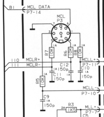
But where should I connect that in my custom cable? Looking at MCL pinout’s answers that question:
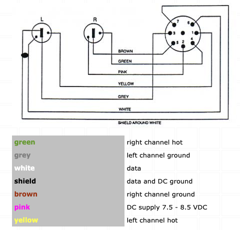
Ground on both speaker connectors as well as data shield is all connected which means that pin 3, 5 and 7 in the BL3500 MCL connector all has to be connected:
BM5500 pin 2 – > BL3500 pin 3, 5 and 7
BM5500 pin 1 – > BL3500 pin 1
BM5500 pin 4 – > BL3500 pin 4
BM5500 pin 6 – > BL3500 pin 6
Tested with the setting ML off in the BL3500 service menu (Menu+0+9+GO)
Success
This is working just the same as with the MCL connection 🙂
Voltage readings on the data pin (pin 6) are the same 4,68V as I registered with the MCL connection
One thing to note from this test is that the BM5500 is the only product where I have found that the data pins in the Aux connector and the MCL speaker connector are connected internally in the Beomaster, so the result of this test might not be the same with other audiomasters.
One other note that I don’t know if has any relation to this is the description of an obsolete Powerlink cable in the Beolink handbook where it is stated that pin 3 and 7 are short circuited. In my head that doesn’t make much sense in a powerlink cable where pin 3 is signal and 7 is data ground, but might make sense if it was used somehow with the BL3500??As we already know that sound input on the MCL port of the BL3500 is possible when a ML source is also connected, I wanted to try if this was also the case if the MCL source has a datasignal.
So I made this setup:
BM5500 – MCL cable – BL3500 – ML cable – 1611 beolink converter – DIN to minjack cable – iphone.
Tested with the setting ML on in the BL3500 service menu (Menu+0+9+GO)
Only the source from the 1611 Beolink converter was available
Tested with the setting ML off in the BL3500 service menu (Menu+0+9+GO)
Beolab 3500 froze and didn’t react to any remote commands at all.
So I guess the conclusion of this test is that the BL3500 can’t handle data signals on both the MCL and ML connector at the same time.
My Beolab 3500 is and MKI (SW 1.2) with the MCL connector. I have used the service manual for the BL3500 (its called LCS9000 servicemanual) available on Beoworld but also a lot of other servicemanuals, and MCL related documentation to get information and inspiration and I will try to mention them as we go along.
To get A baseline for testing I choose to start with a test of the BL3500 in a MCL network as it was supposed to be used to confirm everything working and to know what to expect for certain scenarios. I have a Beomaster 5500 I have used as the audiomaster in the MCL setup.
BM5000 – MCL Cable – BL3500
Tested with both the setting ML off and ML on in the BL3500 service menu (Menu+0+9+GO)
The sources from the BM5500 is controlable, and volume control is possible. This setup seems to be working as expected.
With a multimeter I tried to measure voltages on the different pins, and I got a voltage reading of 4,68 V on the data pin (pin 6) relative to all other pins. The voltage would drop slightly for a second when I turned the system into standby, and then continue at 4,68V. I know that the signal has embedded data, so these measurements might not tell everything.
Use cases via ML connector
Beolab 3500 MKI or MKII connected to Beolink Converter type 1611, two sound inputs controlled with Beo remote via custom cable https://beoworld.dev.idslogic.net/forums/topic/beolab-3500-and-1611-converter-settings/page/4/#post-14017 thanks to Matador for the great drawing.
Beolab 3500 MKI or MKII connected to Almando Masterplay with sound detection input https://almando.com/almando-masterplay.html?___store=endkunde_eng&___from_store=default
According to the user manual for the product, the timer function on the BL3500 has to be active for it to work.
I have no experience with this product, and haven’t read about experience with it.
Use cases with MCL/Poverlink connector
Beolink 3500 MKI MCL connector
Custom cable pinout post number 2 in this thread https://www.hifi4all.dk/forum/forum_posts.asp?TID=32157&PN=1&TPN=30
Beolab activated with Menu+0+4+GO command. Powers of at any other button press so no volume regulaton on the BL3500 or with remote. The MCL connector can be Can be used this way even though a ML source is also connected to the BL3500
Beolink 3500 MKII PL connector
Custom cable Custom cable pinout post number 2 in this thread https://www.hifi4all.dk/forum/forum_posts.asp?TID=32157&PN=1&TPN=30
Beolab activated with Menu+Menu+0+4+GO command. Powers of at any other button press so no volume regulaton on the BL3500 or with remote. The PL connector can be used this way even though a ML source is also connected to the BL3500
Knowledge about the BL3500
Link to BW product page: https://beoworld.dev.idslogic.net/prod_details.asp?pid=373
Link to BW faq regarding BL3500: https://www.beoworld.ouronlineserver.com/faq_view.asp?id=80
Beolab MKI (originally called LCS 9000) has an 8 pin connector on the back marked MCL. serial numbers are lower than 19343452
Beolab MKII has an 8 pin connector often refered to as powerlink on the back, but according to the servicemanaul for BL3500 MKII only intended for use with Beolink Wireless 1 (W1). No pinout for the connector is shown in the service manual other than pin 6 in the Din connector being data. Serial numbers on BL3500 MKII are from 19343452 and up
Not confirmed knowledge about the BL3500
A user on Reddit https://www.reddit.com/r/BangandOlufsen/comments/rvr4f4/best_way_to_modernise_a_beolab_3500_soundbar_as/ apparently has a setup with a BL3500 MKI (SW 1.1) where he is injecting 5V from a USB power adapter to turn It on. User Matator has been in contact with this person who has mentioned that the power is connected to pin 1 and 7 on the DIN connector. It has not been possible for Matador, Guy or me to replicate this in our test’s in this thread https://beoworld.dev.idslogic.net/forums/topic/beolab-3500-and-1611-converter-settings/page/17/#post-16910 Nor with the reverse pin combination (pin 3 and 6) or the dataline and its shield (pin 6 and 7).
if the 1615 can translate ML audio into more digestible DL/AAL formats, couldn’t we attach an AD converter with AUX in to it and use it as a poor man’s “stream any ML source to modern speakers” device?
This hasn’t been tested in this thread as the focus was more on audio the other way into the ML network. Looking at the diagram for the 1615 there isn’t the same switching circitry as in the 1611, so the sound might just drain through from the ML to the AAL connector without any control needed.
@Guy: did you have a 1615? then maybe it can be tested with your Beovision or your beoport if you are up for it?
which commands did you use? With the 1611+MCL2AV combination it was the AV+Video source command or shift+radio+1 that made the sound from the tv come to the MCL2AV
I was mostly trying AV-TV*, but have just tried shift-radio-1 and that doesn’t work either, even if the TV is already on. AV-TV does turn the MCL2AV on (the sensor LED goes out) but the TV does not react either from standby or when already on. *EDIT: I tried all other audio/video commands also!
ok so the conclusion on the 1615 based on your tests must be that it will only work with a Beovision with datalink I guess.
ironically on our local Ebay equivalent here in Denmark the 1615 (and 1614 for that matter) are typically priced higher than the 1611 box…
So I just tried adding the MCL2AV (and IR sensor) and it didn’t work – I tried several option settings on both TV and MCL2AV. But looking at the MCL2AV circuit diagram, pins 1 and 4 are only an output hence effectively I have two audio outputs connected, which cannot work. TV source for this and earlier test was the TV’s internal tuner (which worked over ML before with the BL3500). Regardless of the lack of audio, the BL1615/MCL2AV setup will not even pass control commands to the TV to turn it on etc. So this looks like a non-option!
which commands did you use? With the 1611+MCL2AV combination it was the AV+Video source command or shift+radio+1 that made the sound from the tv come to the MCL2AV
I just tested a BL1615 connected to BV10-32 with ML – unfortunately there is no line output from the AAL. I checked AAL pins 1 & 4, and then 3 & 5 (the latter just in case the service manual was wrong). So it looks like some form of AAL trigger is required. When I get a chance I will see if the MCL2AV (with IR sensor) can provide this. EDIT: I suppose that the TV needs to receive some form of trigger in order to activate audio over the ML, but it needs to receive this via AAL -> 1615 converter -> ML data.
ok seems logical that it has to be triggered. I have to ask though, was it an analog source on the TV?
looking forward to see if the MCL2AVwill also be able to work this way. Could be an alternative to a Beolink Active, but with more local inputs
- usabilty: In general I don’t like these types of online book. Most times I struggle with zoom functions not beeing great, and fast scrooling is just easier with the mouse wheel than with screen buttons in my opinion.
- I don’t think it’s better than PDF primarily because of the above
- No added value for me, but I’m ok with it if it’s also possible to open the PDF file (it’s not possible with all of the 4 you have uploaded).
But great Idea with easy access to manuals from the forums. Keep up the good work 🙂
Interesting – so if I wanted to connect a BeoGram record player to my ML network (I don’t have any product that can control the BeoGram anymore, would I be able to remote control it via the 1611/1615? Or would a 1611/14 converter be insufficient as it still needs a beomaster talking properly to the turntable?
Just to clarify my earlier quick answers: The 1611, 1614 and 1615 beolink converteres are 3 different products. The 1611 is confirmed in this thread to work as a converter between a link speaker on ML and AAL input without any Audio- or videomaster in the system.
The 1614 I don’t know a lot about, but it’s mostly the same, but without the capability to works as a audiomaster in the ML network according to the ML handbook. So you would probably need a real audimaster as well in the system going against the idea of using the BEogram without an audiomaster.
The 1615 is only for connection a link room Beovision without ML connection to a ML network and recieve audi signals from the audio and or videomaster in the ML network, and therfor as describe earlier only on way audio from the ML network to the Beovision, and therefor not useable for your case.
The MCL2AV will work as a “light” audiomaster and can convert the AAL control signals from the 1611 to AL signals that can control the Beogram via the ML netwrok. Further the MCL2AV can have a IR eye and speakers connected for local control and listening if that makes sense in you setup.
Also, in that linked thread the Beogram was a ‘local source’ but I would hope that the BL1611 would make if available across the whole system.
I am pretty confident that it should make it available on the ML network as my test with my Beocord 3500 has shown I can control it from a BC6 via the 1611 and MCL2AV.
If you dont want a beomaster you can use the MCL2AV to convert AAL from the 1611 to AL to control the record player. The chain would look like this:
ML-1611-MCL2AV-Beogram
The MCL2AVdont support the phone command, but for its inputs, but CD can be used
Quick question for the “1611 creative use SWAT team”
I can get my hand on a 1615. Now this box obviously only has the AUX port. But other than that: would this box allow my similar stunts to what you guys are pulling with the 1611? cheers Torsten
It hasnt been tested in this thread, but Guy concluded based on the servicemanual that it is only One way ML->AAL
So I guess you better look out for the 1611
One little update regarding the MCL/PL connector in the BL3500.
I have been a little confused since Keithe mentioend that the PCB’s wasn’t changed when the MK2 version was made. Especially the pinout differences between the MCL connector and a PL connector was illogical where the signal and GND pins are different
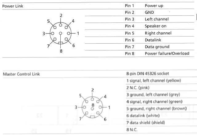
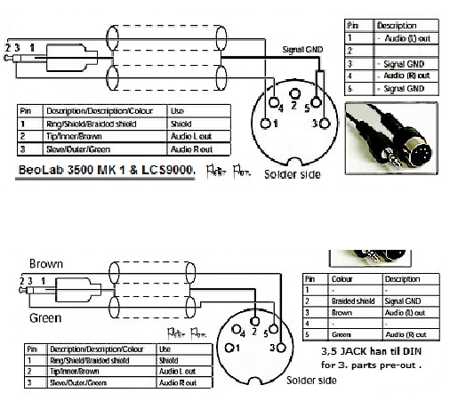
Also Peter Pans drawings indicated that (MKI top MKII bottom):
I looked at the wiriring diagrams in the servicmanuals for both the MKI and MKII several times and notices that also here the signal pins and the GND pins is reversed (MK1 top, MKI bottom):
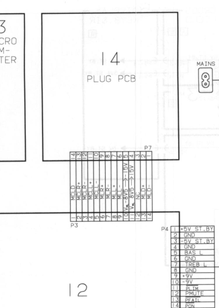
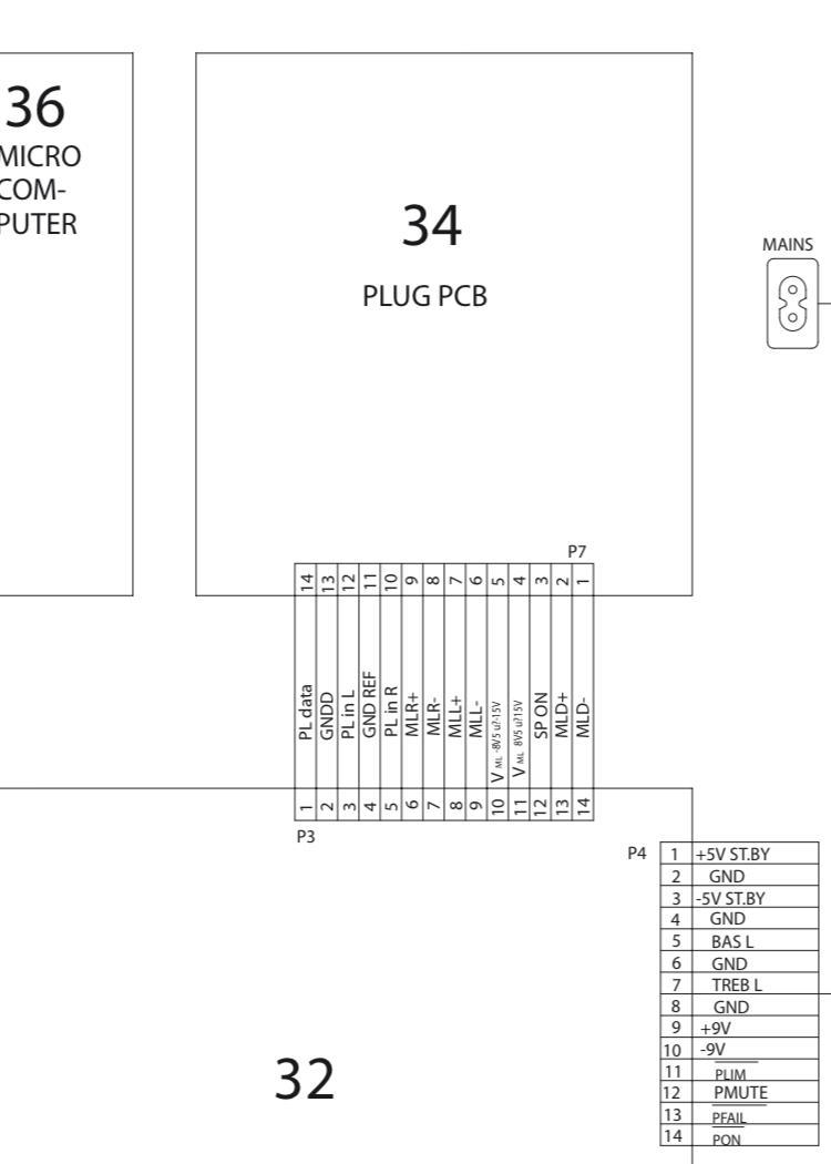
So I thought if the PCB’s are not changed can the pinouts be reversed. I had earlier made a mini jack to DIN conenctor like the Peter Pan one for the MK1. So I tried to switch the pins and put the signal lines on pin 3 and 5 and the GND on pin 1 and 4. Activating the BL3500 with the Menu+0+4+GO and the sound is comming through and I can’t hear a difference between that pinout and the pinout I had before.
So as for signal lines this suddely makes it very similar to the powerlink conenctor. It doesn’t make us wiser on the 5V power on thing, but it might be a piece of the puzzle
I agree with Guy that you might need to go the ML ->1611 way to get an input with some kin of datalink that you might be able to communicate with.
A couple of source regarding datalink:
1.
Article on the Beotech section on this site: https://beoworld.dev.idslogic.net/beotech/datalink.htm
The linked datalink manual linked to on that site is not availebale there, but can be found in the manuals section if you upgrade your membership.
2.
A readme file for some Github projects regarding datalink. https://github.com/toresbe/datalink
he refers to it as datalink 80 and datalink 86. As far as I have found out datalink 80 is also what B&O call Audio Link which is the communication used between a Beomaster and tape/CD/phone. Datalink 86 is then what’s called Audio Aux Link which is the communication between Beomasters and Beovisions or in this case the 1611 converter.
As for how the inner workings of the communications work I have no idea, but hope you can get something out of these sources.
If you still need to connect airplay/cromecast as you mention in your first post you could always try if the 1611 coverter will give you an extra input or two
The Beosound Ouverture in the cabinet as since then be replaced by a Playmaker for streaming, including radios. It drives the BL8000 but also a Beolink Passive and a pair of C40 in the back. The Ouverture you see in the pictures is just there for when/if I need to listen to a tape or a CD. And also because I have no other place to store it!
Ahh then you are all covered with all sources in this setup 🙂
Very nice looking setup. I like the detail with the lamellas on the cabinet.
If you still need to connect airplay/cromecast as you mention in your first post you could always try if the 1611 coverter will give you an extra input or two
Did we have other combinations in play?
Have you tried these pins with ML both ‘off’ and ‘on’, using MENU MENU 0 9 GO and up/down arrow? I suppose it could make a difference (not that I noticed any with mine, but mine is SW2.0, and your SW1.2).
just tried that with the three same combinations. No luck again.
just a note I have no sound source connected, but Iexpect that the display should show something if its on?also checked the SW version in the service menu, and it is indeed 1.2
One thing we havent considered is that the guy who succeded with this might actually have a modified unit without knowing it.
At some point I will try to open my BL3500 up and see if I notice anything we cant decode from the service manual
- AuthorPosts
