Forum Replies Created
- AuthorPosts
-
Thank you again. just for an idiot guide and to be totally clear, you mean shield are the bare wires that surround the coloured wires inside the cable when I cut it back? there is no other bare wire or wires so I guess that’s what you mean?
That is correct
Shield is the bare metal wire
Take a look at this post fo the pinout. On some connector the numbers are engrave in the plastic
https://beoworld.dev.idslogic.net/forums/topic/wiring-diagram/#post-25003
I have opened up the DIN connector on a broken Beogram 2000 I have and these are my findings:
Blue and thin black wire is not connected. Thick black wire is connected to the metal part of the plug
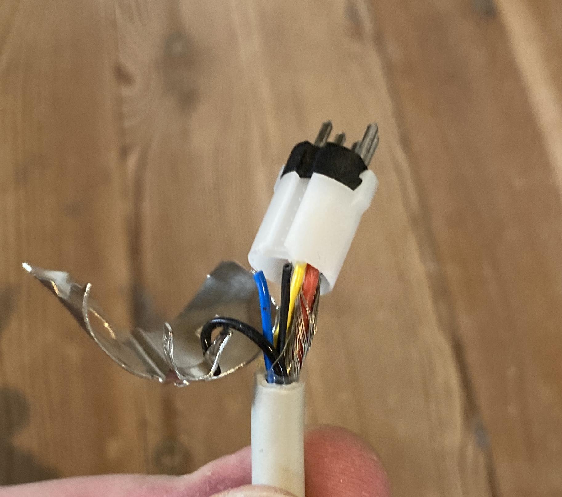
Shield is connected to pin 2 in the DIN connector, red to pin 5 and white to pin 3 (note that pin 6 and 7 is unscrewed in this connector)
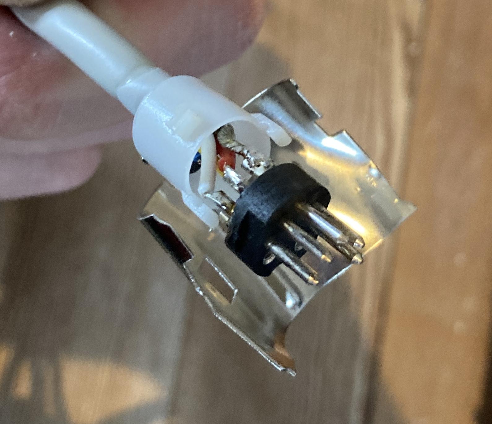
Yellow is as you have noted yourself datalink and is connected to pin 6
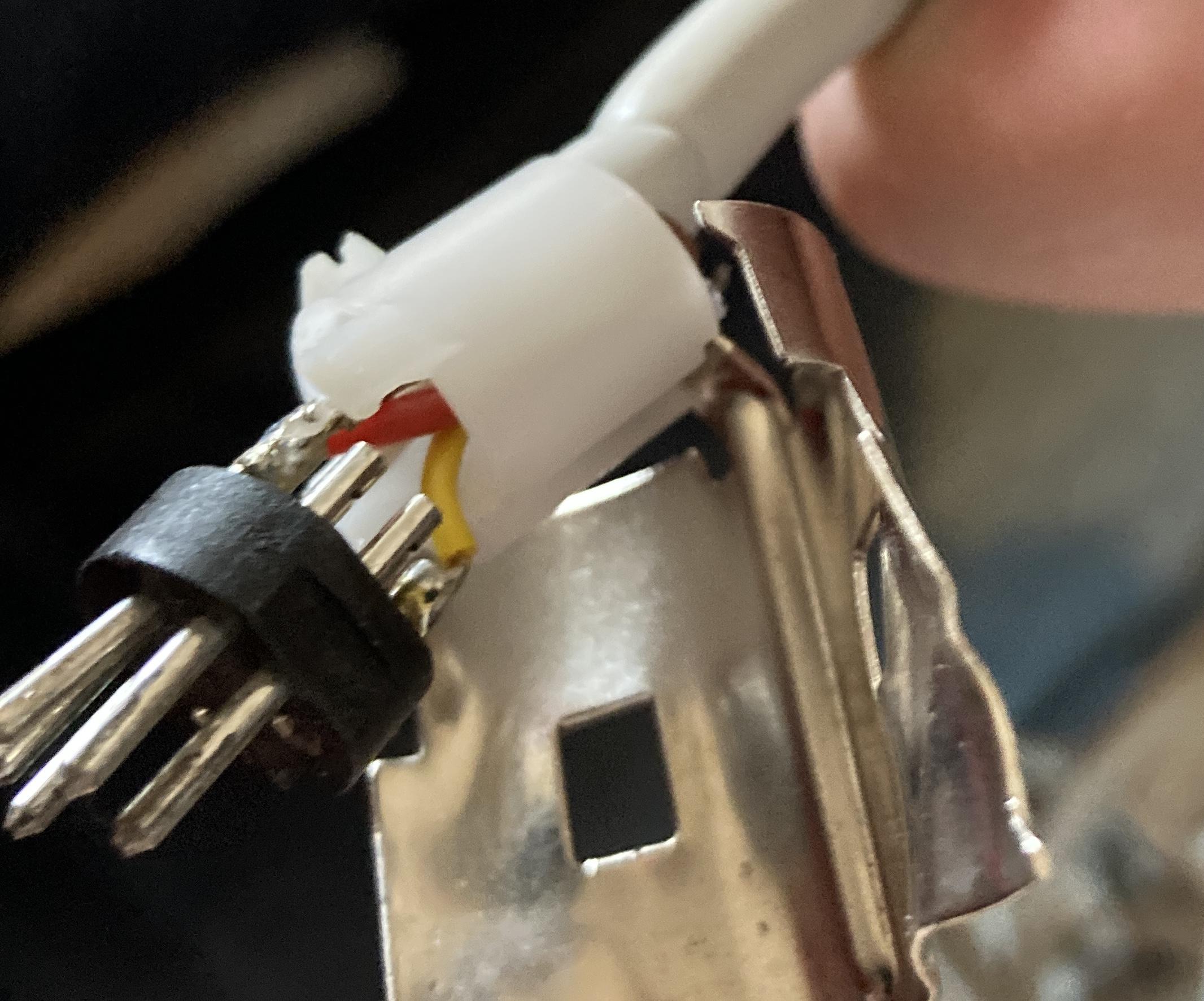
Hope this helps in getting the Beogram functional again
It’s thread drift for this thread, but I am helping a relative sort out some tech/AV gear and have a Google Chromecast HD for a few days. I just tested it with my BV10-32 and realised that you can setup the Google Chromecast remote to control the TV’s volume in the same way that a siri remote does! The Chromecast menu also offers the facility to turn the TV off/on (I could only get ‘off’ to work) and to change inputs, but I couldn’t get the latter to work. I am quite impressed that such a cheap device (£35 in UK) has the IR codes to control a Beovision!
It is indeed quite interesting how both Apple and Google are integrating these B&O IR codes. Maybe they are just using common libraries of IR codes that are available. However in case of B&O they also need the transmitter to be able to transmit 455Khz IR codes that other brands are not using, so I guess the hardware must also be made for it.
Sound like the Google Chromecast is not perfectly working though which was also the case with the 1st. Gen siri remote.
Just read your post again, and can see that I did not get the turntable in the cabinet in my first reading.
It could be a Beocenter 7700 wich also fits the description of the remote
https://www.beoworld.ouronlineserver.com/prod_details.asp?pid=407Bang and Olufsen really have had many systems with smoked glas and red LED lightning. Just a few examples here that might hint something more:
Beosystem 6000
https://www.beoworld.ouronlineserver.com/prod_details.asp?pid=1253
Beocenter 9000
https://beocentral.com/beocenter9000
Beosystem 4500
https://www.beoworld.ouronlineserver.com/prod_details.asp?pid=419
yes, the beogram has a 7-pin Din connector and the cable looks original and cannot be unplugged. But you are right, the problem is somewhere at the beogram. Attached are two oscilloscope traces from the overture aux/pin 7. It sends 2 times the same ‘start’ signal. Interestingly, it is the same sequence – once triggered by pressing AUX in the overture or PHONO on the Beo4…. Looks like I have I have to open the Beogram……
Have you also tried to measure at pin 6? Pin 6 and 7 should be interconnected at the Ouverture, but just to be sure.
A beogram without RIAA use pin 6 for data.
Beo-museumSomething like that 🙂 my little limited space for toying with those beatifull things.
According to service manual of BC6-23 MK1 type 9212-9218: Softwareprogrammering – Programmet M2 – STB-C-tabeller NB: Anden software end ovennævnte kan opdateres ved at udskifte EEPROM’erne i hovedmikrocomputerens modul 6.
Doesn’t say much about functionality though. I wonder what the program M2 is?
Space constraints. From 26″ to 23″ – that must be a tiny space. Sorry for the off-topic answer. Couldn’t help it.
Yes it sounds weird I know, but here the 23″ is placed. The 26″ would be crammed in between the window and the angled wall
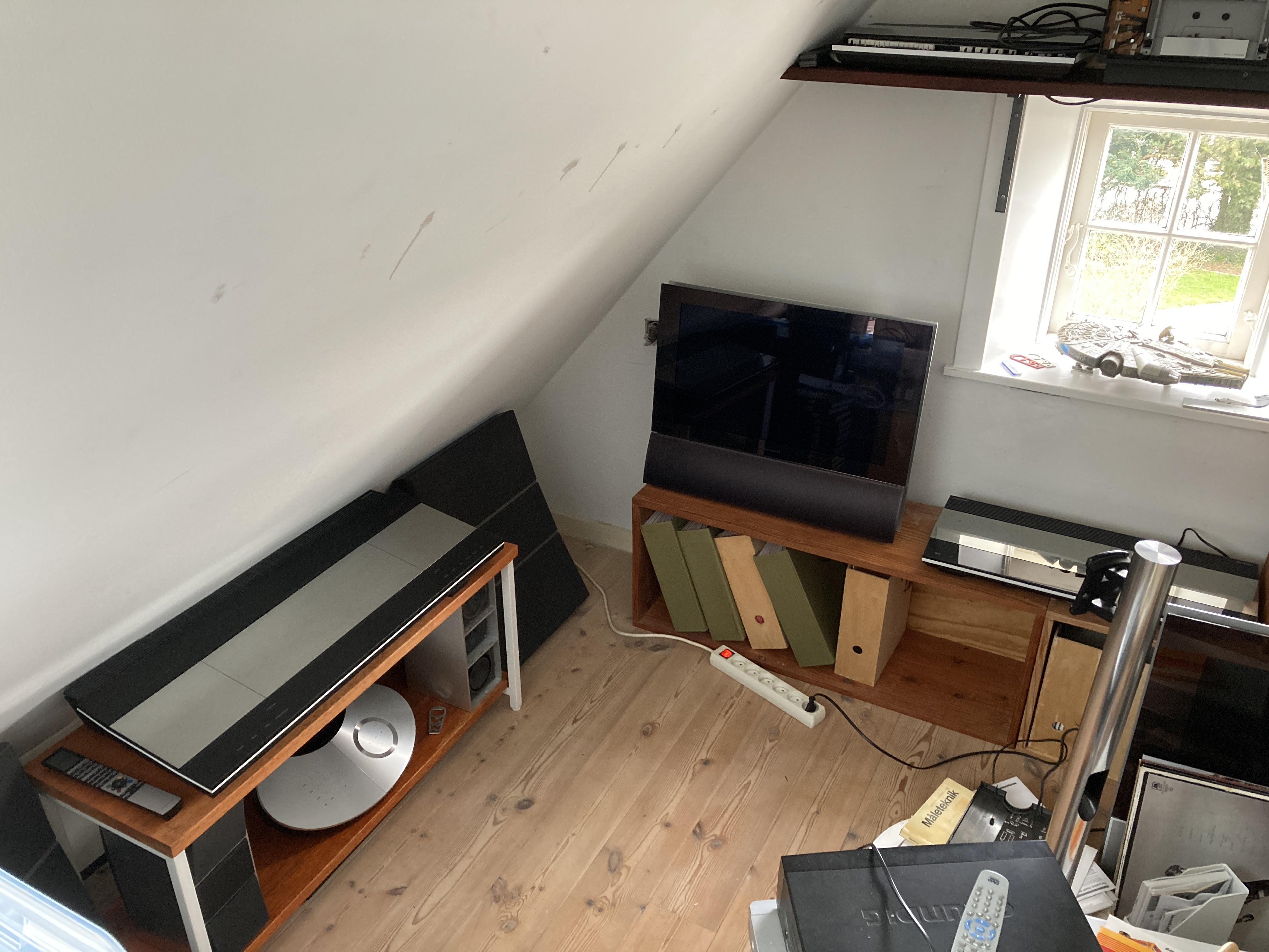
Since these TVs are worth 0 now a days… It might be easier and cheeper just to get another Beovision 6-22 or Beocenter 6-23 …
Thats true. Not many available on local adds at the moment though, but I might keep looking.
If anyone else have insights regarding the updates I am still interested to hear about it
Hi, I have a similar problem. BS3/BV9 connected via masterlink to an Overture. BS3 – option2; Overture option 0 or 2. The Overture is (with the original Din 7-pin cable) connected to a beogram 5500 via the AUX input (in the moment without preamp – will be added later). Sadly the beogram cannot be remote controlled. Could be the reason, that the beo4-remote does not sent phono-commands, as it just offers AUX over the list button?
You should be able to add the command “PHONO” or if it’s a newer BEO4 “N.RADIO (the same command) to the list.
Press and hold “Standby” + “List” and the display on the BEO4 should show ADD
Now press “GO” and press list until you find the command you want to add. When you are on the command you want to add simply press “GO” and it should now be available in the list.
Hope this helps
Thanks, I added Phono to the list on the Beo4, but still, the beogram 5500 does not react. Pressing AUX on the overture shows AUX on the display and I can hear sound when starting the BG anually – connection is OK. But from what I read in other posts, the overture should then show PHONO as it recognizes the beogram…..correct? IMHO – very strange, as it is reported to work. Arguably an HW defect…i.e. the cable does not have the datalink pin connected – but it looks original and is not removable from the BG.
Do the DIN connector on the Beogram have 7 pins or are some of them missing? Normally the 2 pins in the button can be unscrewed, and one of these carries the data control signal
My friend opened up his V1 today and sent me some pictures from the inside.
Although the mainboard look a lot like the one in Guy’s V1 I not spot a component that could be a battery although the marking C304 suggest a capacitor.
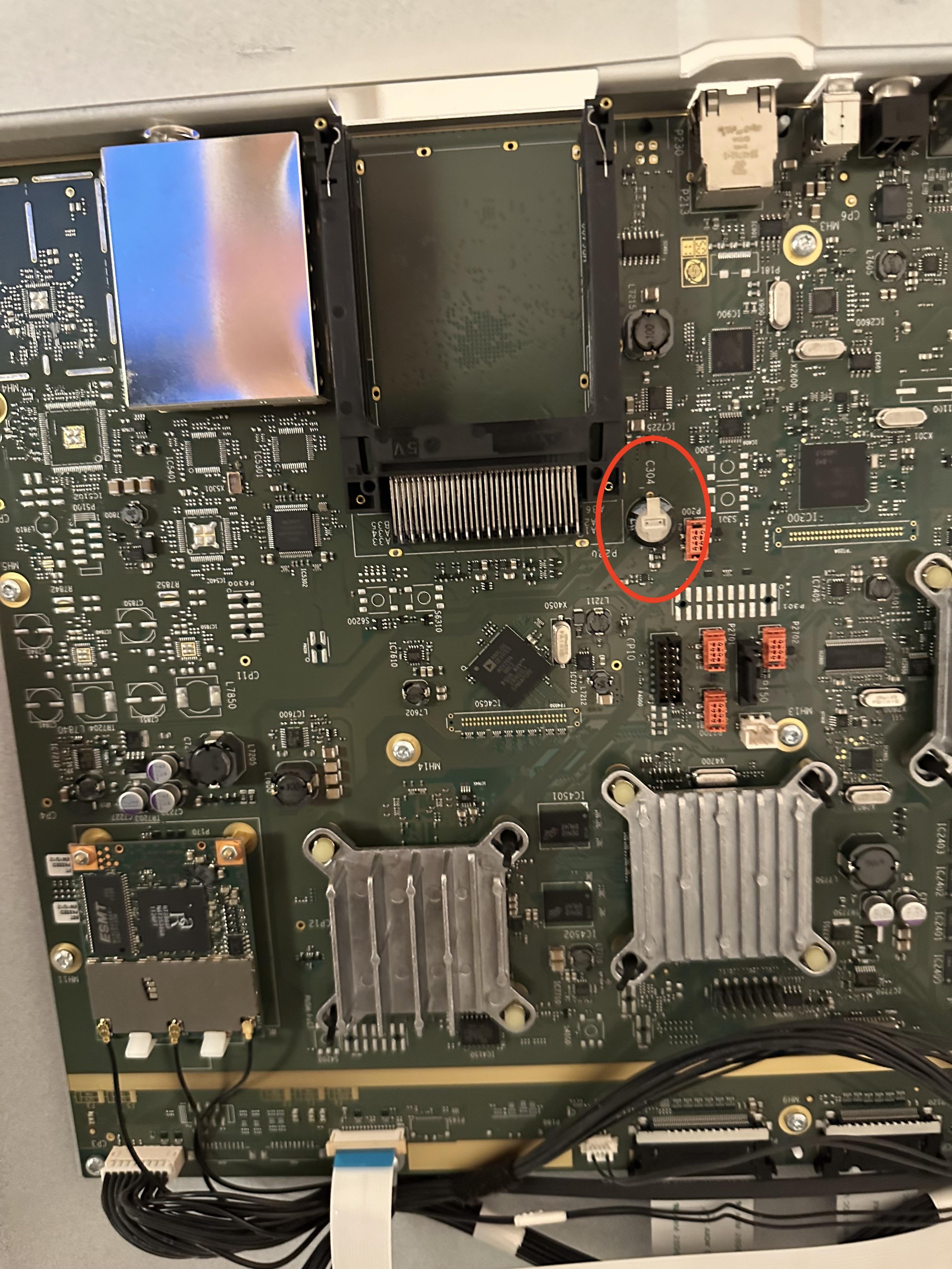
And from a slightly angled view
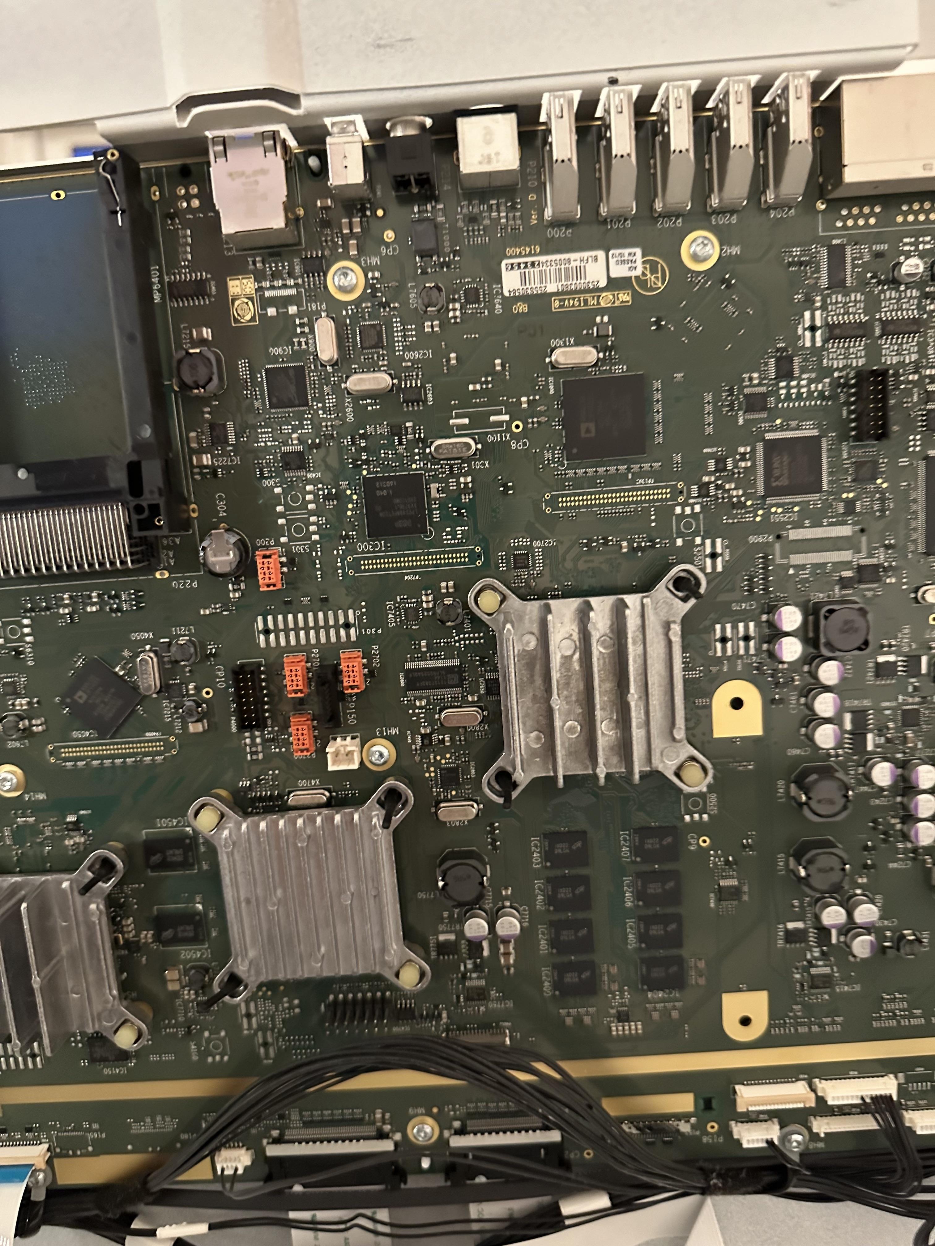
There are no visible leaks from this component, but that of course does not men that it couldn’t be defect.
Any thoughts
When I first opened mine it was screen downwards on an old cot mattress. I re-inserted the top part of the bracket so it could pivot (unfold) upwards. I then reversed the tv so that the back was downwards and the screen carefully pivoted up.
Thanks. Thats a very helpfull view of TV opened up. I do not spot a battery here either, but could of course (why place it so it is easy to get to) be placed on the other side of the PCB. My best guess would be that it is placed on the large mainboard as the function is probably to keep data when the TV has no power.
Other possible culprits could also be capacitors on the PSU board. Your photo shows two large ones placed in openings in the PSU board.
I can only assume that those sheets would protect from scratches caused by opening the plastic ‘hinge’ beyond its normal range of movement.
Maybe it is more nessecary if the TV is opened up 180 degress. I guess that B&O’s description of it is to be 100% sure that a service technitian do not make scratches when he is working on it.
Well I found them for 2€ or so in a trift store where they did not know what It was. So if you pay the postage cost I think that will be fine.
Could you drop me a PM with your location, and then I can find out the postage costs
A little update for usecase 8 where a Beomaster 4500 is used in a link room.
I found out in the Beolink system manual that when the Beomaster 4500 is set to option x.6 powerlink and MCL data is disabled, so only passive speakers can be used.
For reference the lenght on my set is 7 cm
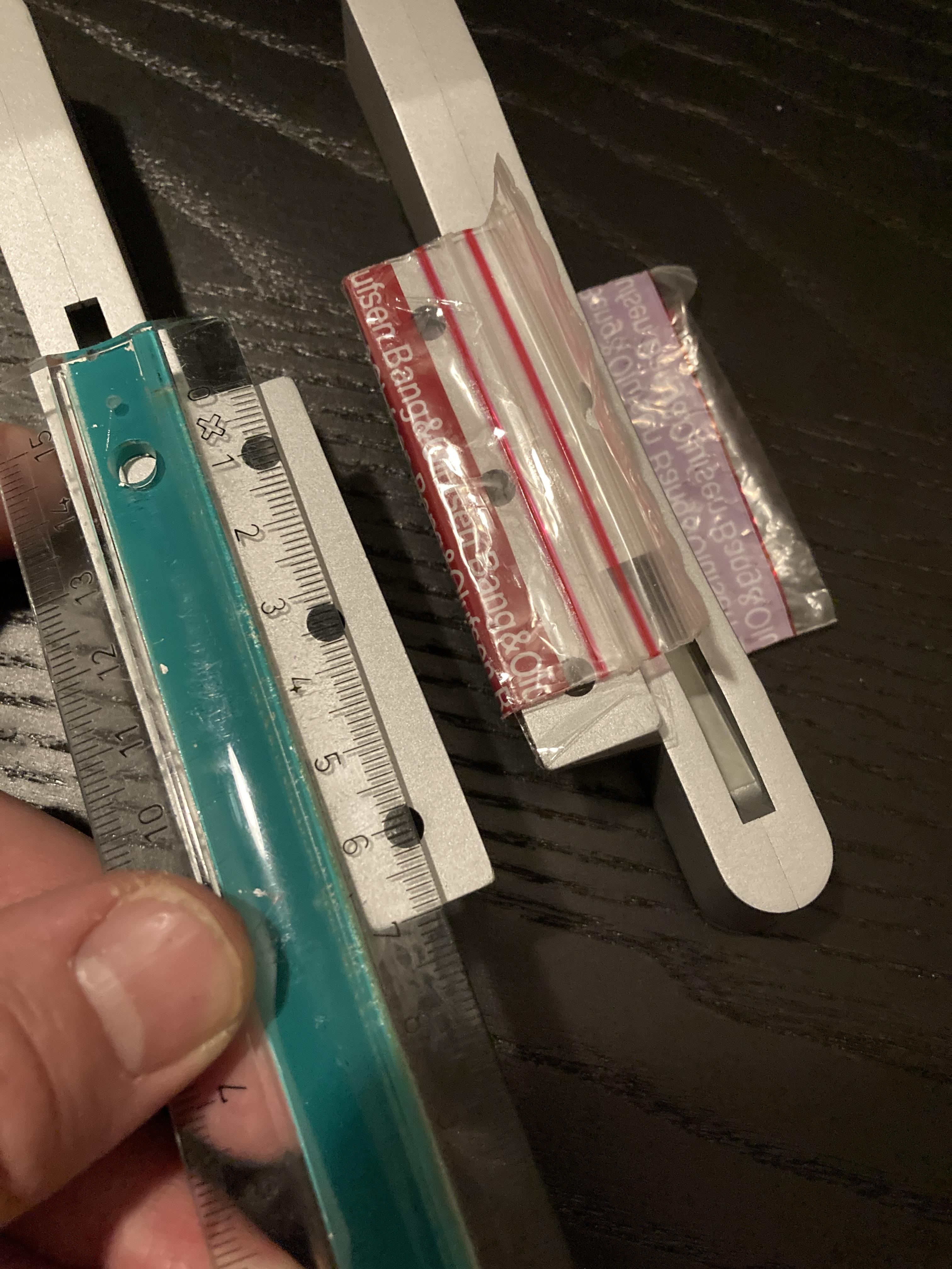
I have a set lying here.
I am not sure if there is a difference in size whether it’s for a 26″, 32″ or 40″, and I don’t know which size mine might have come from.
Could you measure the lenght of the recess for the feet on the bottom of the TV
The oversight in the design seemed to be though,that you needed to switch the second pair of ‘speakers on/off via the transceiver manually,and could’nt ever have just the remote room ‘speaker operating.
Great with some info from one who had hands on experience with this link system.
When you say:
you needed to switch the second pair of speakers on/off via the tranceiver manually
Does that mean that you have to do that before you can use the remote control?
We used to get around this by reversing the speaker 1/2 connections,as the sockets are cabled in paralel.Speaker 1 (main)then can be switched off via the 2 switch under the cover.
That kind of break the idea of remote controlling in separate rooms. But fortnuatly that got better in the newer link systems 🙂
so I opened up the TV and searched the PCBs inside
How did you approach the opening of the TV?
The reason for asking is that the disassembly instructions mentions insertion of protection sheets, and I wonder if that is of a specific material or if it could just be a piece of paper or cardboard?

I guess the purpose is to avoid scratches on the painted surfaces
so I opened up the TV and searched the PCBs inside, and found nothing remotely like a battery!
A pitty. It could be nice to know where this battery is placed, and if it could be DIY replaced.
Worst case if it is like some batteries used on 30 year old computeres, the PCB traces could be destroyed by the battery acid.
- AuthorPosts
