Forum Replies Created
- AuthorPosts
-
I only have a picture, so I can’t look around the component.
But I believe you are totally right Martin. Your explanation makes perfectly sense!
Thanks again. I am getting closer to have all information for replicating the original!
#22 & #34:

#31:

Thnx a lot Martin, clear!
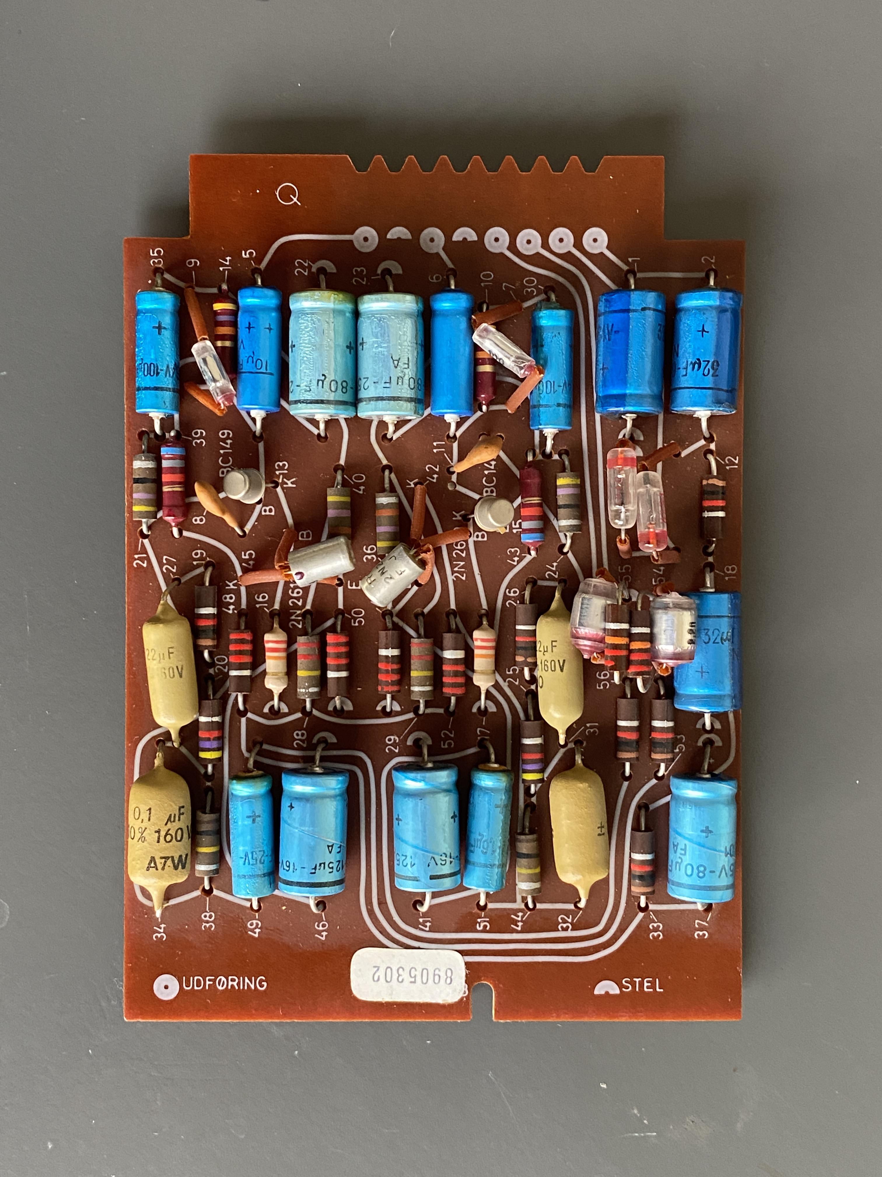
At the bottom right on the PCB, there’s two light brown capacitors: #27 & #34. And on the other side there also two: #31 & #32.
The schematics says:
- #27 = 22n
- #31 = 22n
- #32 = 0,1u
- #34 = 0,1u
The picture of the components says:
- #27 = 22uF, 160v
- #31 = 22uF, ?v
- #32 = ??, ?v
- #34 = 0,1uF, 160v
Questions:
- I guess the picture is right and the schematics to be ignored on this point?
- Are these ‘Orange Drop’ Capacitors?
- Are they all 160v, and this it matter of the voltage of the replacement differs?
- I guess #32 is also 0,1uF?
Thanks for sending the bottom view picture!
Yes, I am aware that my trace image has to be mirrored.Question
The board side that sticks into the slot (so where the 8 tracks in a row are), has 8 notches.
Can you please let me know how deep they are?I think they are a little less deep than the 6mm notch on the other side of the board.
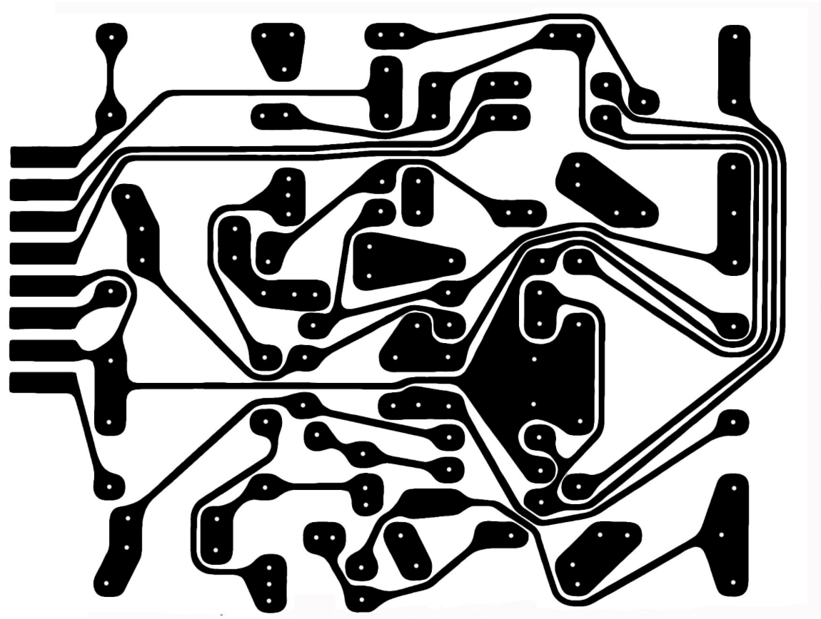
At the moment I am in preparation of making the PCB. My first step is to get the copper traces on a board.
Therefor I have to position and size the image of the copper traces perfectly. I have that picture (see picture below), but it has no outer/PCB border lines, so I have to find out how to size and position this image. (Obviously to get size and proportion equal to the original PCB)
Questions
- Does anyone have such picture of the copper traces pattern, including outside/PCB border lines?
- @Mexking: do you have a picture of the bottom side of the pre-amp board?

Update:
I have now collected most information to reproduce the original B&O BeoGram 1000 RIAA pre amp extension board.
- PCB layout (including drawing of the copper traces)
- Components & specifications
- All dimensions in mm of the PCB board
1 & 2 in this post.
3 in this thread:About components, I will continue in the next post in this thread.
This is perfect information, thanks so much !!!
I will start to re-produce the original BeoGram RIAA preamp.
Fantastic!
That is a way of course. Measuring the slot size, and calculating the other dimensions from there.
Maybe I will post a seperate question for measurements. I guess someone on the forum will have a board, to measure all sizes. If I find those, I will post here what it is.
Thnx
Thanks very much for sharing these pictures! That makes it a lot easier to try to make one myself!
Question
Since I do not have a pre-amp board at hand, do you have the outside dimensions of the PCB?Thanks all for your responses and contributions!
I have been questioning that myself too. If I look at pictures of the pre-amp board, it seems it is not unthinkable to re-make it. Even in the same look & lay-out as the original. It even makes me wonder if maybe someone did that … (?)

That’s a good suggestion! I will check with Dillen.
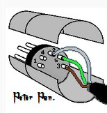
Thanks for referring to Peter Pan’s diagrams Guy, that made it clear!
I like the visual way of understanding the pin layout. In the end, it’s easy to make a mistake if you don’t understand the interpretation of sides: male/female and pin/hole side or solder side.
So a picture like Peter Pan is using, helps a lot:

Just to be sure …
When looking at the picture you added about the pin-numbers and what they mean:
- Is the view of this picture, the male connector from the backside (soldering side)?
- Are the ground wires (of the input and output cables that I need to combine to the DIN), combined on PIN 2?
I would also be interested, and to know of there’s an English version.
Of course, I understand its Steve’s business. 🙂
But I do not have to know how the cable has been configured internally.I just want to understand if this is only a Mini-Jack-to-DIN cable …
Or that it comes with something else for the 5-volt/trigger signal.@Steve: maybe you like to respond to this?
Did you connect a Powerlink or RCA cable to one of the connectors?
what do you see and hear when you do that?
@Steve
Very interesting the Mini-jack to RCA cable also has a trigger signal.
But for my understanding, the trigger signal needs to be 5v on Pin 4.
Where do you get the 5v to be used on Pin 4 to activate the B&O speaker amp to get from stand-by to active? Hoe does that work with this cable?
Hi Lawso,
1) What do you prefer; a) to have an external device to add streaming capabilities, or b) an internal integrated solution?
2) To which B&O model would you like to add these capabilities?
@Steve
Great comment Steve.
How does the (for instance) Apple Airport generate a trigger signal for the BeoLab?
By the way. Is it possible to see the linked product when your website is temporarily closed?
I understand your not 24/7 available to follow-up on everything. Though I can imagine that you keep all informative parts of your website accessible, and close ordering and contact form. Would that work for you?
Thanks for your replies guys!
I mainly wanted to know if the pin 3 & 5 and pin 2 & 4 would work simultaneously. So thanks for confirming.
Concerning the cable … the one I need will look a little bit different. I need to split from DIN to a) mini-jack and b) RCA female. But that’s no issue for me, to make one myself.
Thnx to all, this is a great experience to have such great responses so quickly on the BeoWorld forum!
Additionally I should mention, the external recorder is non-B&O. It will be a vintage Nakamichi 600 cassette deck.
Not being able to control this external recorder as a B&O device is not an issue. For me it is just important that there is a L & R channel OUT, that I can pick up via the Auxiliary connector on the back of the BeoSound 3200.
So from all your information I conclude it is possible and will work. As long as I use:
- Pin 1 > Left out
- Pin 2 > GND
- Pin 4 > Right out
As mentioned and described in the response and picture of Matador.
Thanks!
- AuthorPosts
