Forum Replies Created
- AuthorPosts
-
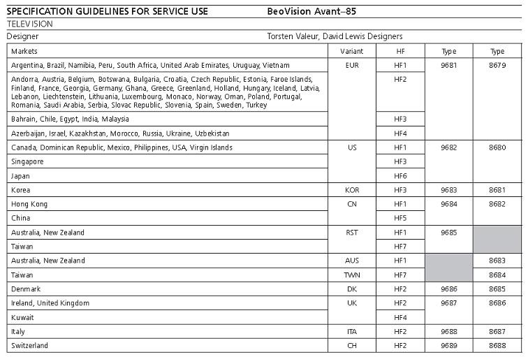
Type number 8686 and 9687 are the same UK product.
I don’t know what Type 8870 is, but it is not an AVANT 85
 7 June 2023 at 08:55 in reply to: BeoLab 8000: request for very first version of the Service Manual #47040
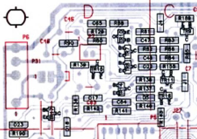
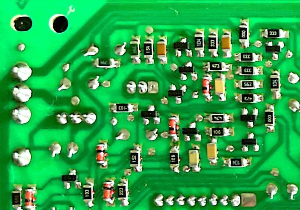
If you expand the physical board layout and the drawing you see that the printed circuit track layout is quite different in the area of concern.
i was also a Gold Member and and had a F as Founder, but now only Bronze Member. Thanks Theo
You are a Gold and Founder Member
Your Membership ID is 554 of 50,229
Your Founder Membership ID is 160 of 500
Ernst,
Thank you for your feedback and I have to say it is a difficult problem to understanding based on the information we have to date.
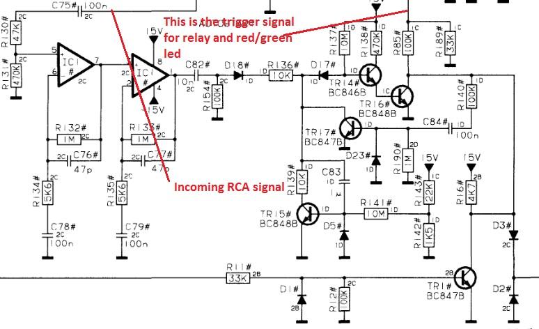
Having said that the basic circuit operates otherwise the system would not trigger with the impedance of your multimeter. This leads me to think that we have a high resistance or open ground connection within the auto start circuit.
At the start of this thread you did mention that the unit was dead with no red light and after you put everything back together you got the red light meaning there was some connection made which was previously not made.
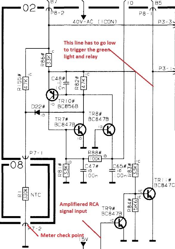
I suggest you check all the ground connections that use plug and socket connections particular associated with the auto start circuit. With the power off and your meter set to resistance connect one meter lead to plug 7 pin 2 as shown below and then check all other ground points have a connection i.e. no resistance.
I’m joining the choir of Gold members showing as Bronze member in the forum.
Apologies, now corrected.
Soon the software to renew/upgrade and payment will be implemented directly on the forum which will remove the current manual process.
I have gone back again and reviewed everything that has been done to date.
A couple of questions came up:-
- When you use the multi-meter which triggered the relay and you heard music, did the LED go green?
- In the last post where you measured 52 volts was that with signal connected to the RCA socket?
It is clear that the problem is in the auto-start circuit and nothing to do with the relay circuit area.
Going back to where you were testing at D1 you said:-
- Interestingly, with the red probe on the top and the black on the bottom: the relay clicks, the Amp turns on and music can be heard coming from the speakers.
Can you please go back and see if you can reproduce this situation.
Hey – I also show as Bronze member but am in reality Gold member. I am sure the programming will work out at some point.
Apologies that you got missed which I have now addressed.
Keith..
Question I assume, there is something wrong with the auto-start and RCA combination. Please advise, what I can do next?
I agree as I previously said…
I cannot help you at present because I am travelling and therefore without circuit diagrams etc.. I will be back from New York late next week..
(I will note, it is a shame that known probable fixes for problems are squirreled away behind memberships. Hardly in a good natured spirit of helping people really)
We would not be here at all to help you and other people if members did not pay to become silver and gold members.
Keith..
Before going into possible circuit problems, lets look at the simple things first.
Is it possible that the switch is set to “left” or “right” rather than “line”?
Well, that certainly looks very clean, perhaps even new form?
What is the 4 digit type number of your Beolab 4000?
Das Problem können die Sensoren sein, die die Schlittenbewegung stoppen, wenn jemandes Hand im Weg ist.
Dies kann oft eine Frage der Reinigung der beiden Sensoren und des Glases von innen und außen seinThey are from 2005 so they do NOT have the foam rot problem.
Are you sure?
Have you taken the speaker down and looked inside. The symptoms you have described are not uncommon and I think you need to open the speakers up to be sure.
And the sheet refers to a “special” Beo4 Remote ?
You only have the two options and the procedure provides the instructions for both.
- Get hold of the “Special Command 2” Beo4
- If you have a Beo5/6 and you load the XML file which I built 11 years ago and I can supply.
If you do not have one of above, then you will not be able to make it region free.
There is a technical bulletin covering this problem with full details in the Beoworld technical library HERE for silver and gold members.
Whilst the region setting can be change with the service tool, its not a requirement.
Eleven years ago I wrote the attached document and made an XML file for the Beo5/6.
Attached is the Procedure for setting a Beovision 7 & AVANT DVD to Region Free
Concerning the D1 diode Keith, can I just order a ‘1N 4148 diode SMD type’ ?
Yes, you could assuming you have the facilities to change SMD type components. You could also use a standard size diode if you have the same type or a similar one and remove one end of R1 or D1 if that is possible.
First of all, after my last checks I put the PSU/AMP-block back into the speaker casing, and connected everything back to original.
Surprisingly, the red LED went ON again! So that’s good.I looked back at what you said in your previous post and I asked myself given what happened and subsequently using the meter trigger the relay did you also have a ground return issue?
Just a thought and observation..
I sent you an email with the background to the problem.
Apologies for your status was not on the Forum, but I have updated the forum now.
Since implementing the new forum members status is not automatically transferred from the web site to the forum, so that currently is done manually.
Very soon our new payment system will be in place and then status updates will go back to being automatic.Apologies.. Keith
Interestingly, with the red probe on the top and the black on the bottom: the relay clicks, the Amp turns on and music can be heard coming from the speakers. I found that the D1 is a type 1N 4148 diode. So I probably need to look for this one as a SMD type. Like to hear what you think Keith. Could this be the cause and is it just a matter of replacing it? Or could there still be another underlying cause?
The fact that the impedance of your meter was able to trigger the relay tends to mean that a component has gone out of tolerance rather than being totally faulty.
Clarification Points
In your last post you said “I currently do not have equipment to connect via MasterLink” I am assuming you intended to say “Powerlink” rather than “Masterlink“?
Also you said “Plug 3, pin 1 <> pin 2 = 24 volts” which is excellent because that should have triggered the relay. Was the RED light on when you checked this?
Next Steps
As you are using the phono input and taking into account the information in your previous post it is most likely that the fault is in the “Auto Start” section or the D1 diode is not within tolerance or the relay itself.
If you are able to replace the D1 diode with a suitable replacement I think it would be the next step. The negative end (plug 3 pin 1) of the D1 diode is directly driven from the “Auto Start” circuit which takes your source input on the RCA socket. You could therefore also test between plug 3 pin 1 and plug 1 pin 2
Well, it is excellent that you have 44 volts between pins 1 & 3 of plug 2
So, the fault is either going to be one of the following:-
- The 24 volt relay itself is faulty, less likely, but possible
- The D1 diode across the relay coil is short circuit
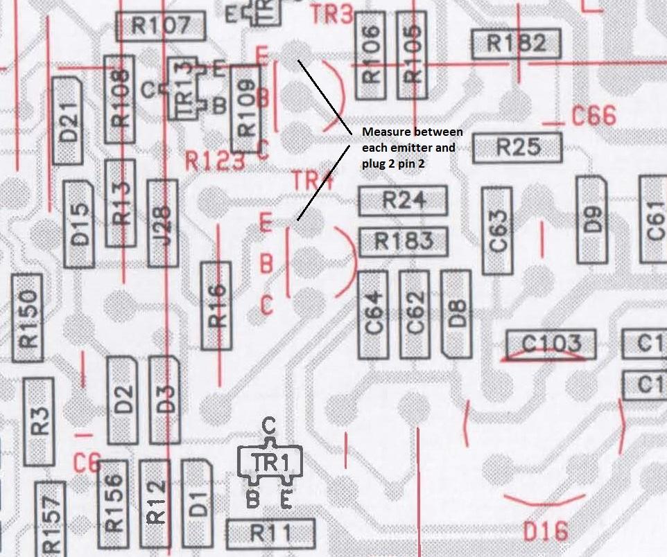
- The + 15 volts is missing from the emitter of Tr3
- The – 15 volts is missing from the emitter of Tr4
- The “auto start” circuit used when using phono socket is enabled has a fault.
Check points 3 & 4 first by measuring between a ground point such as Plug 2 pin2 and the emitter of Tr3 (+15 volts) and then Tr4 (-15 volts)
Measure the voltage between pins 1 & 2 of plug 3 on the power supply module
If +15 and -15 volts are correct, but there is zero or near to zero volts between pins 1 & 2 of plug 3 then the “auto start” circuit may the cause.
- AuthorPosts
