jacek1313

Forum Replies Created

Viewing 7 posts - 1 through 7 (of 7 total)
  • Author
    Posts
  • in reply to: Beoplay V1 screen error #55807
    jacek1313
    BRONZE Member
      • Topics Started 0
      • Total Posts 7

      I had to replace the LCD screen. It is also possible that there is damage to the driver board under the LCD housing. Large selection of cables on Ebay.
      LTA400 Drivers

      LTA320HF05_2__

      in reply to: Beoplay V1 screen error #55802
      jacek1313
      BRONZE Member
        • Topics Started 0
        • Total Posts 7

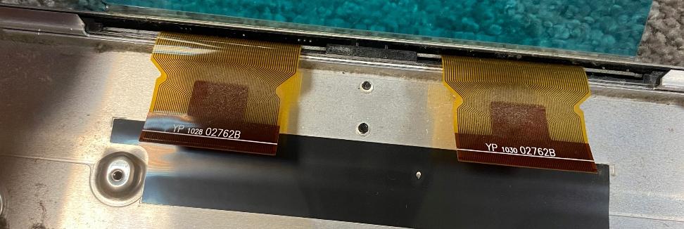
        In the BV10-32 I once repaired, I had a similar defect, a damaged LCD screen. You can disassemble the screen and check the ribbons connecting the T-Con – LCD screen.
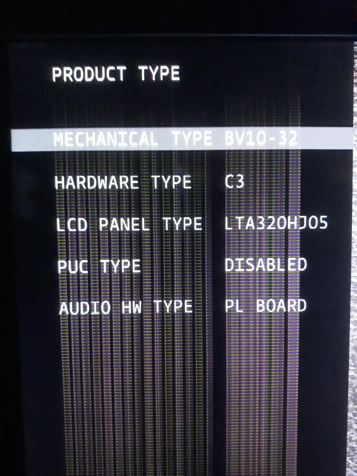
        BV10-32 LCD LTA320HJ05 Org 92 pins

        in reply to: Beoplay V1 not turning on #55586
        jacek1313
        BRONZE Member
          • Topics Started 0
          • Total Posts 7

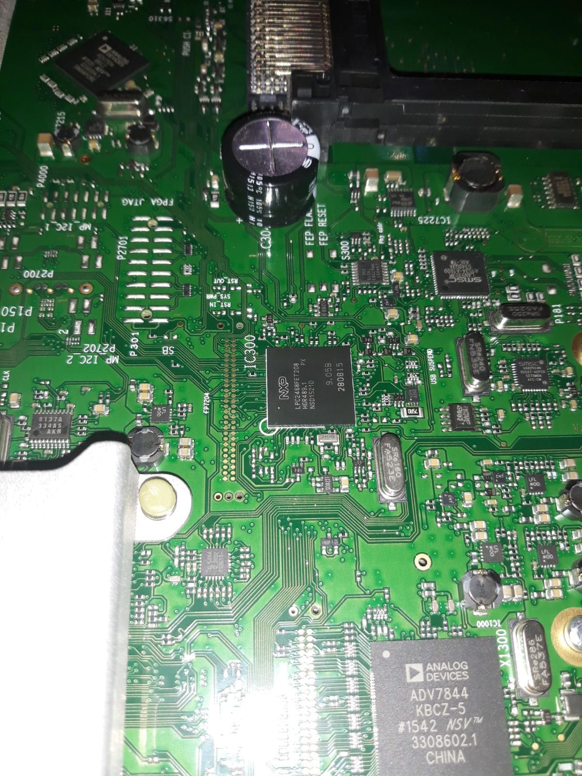
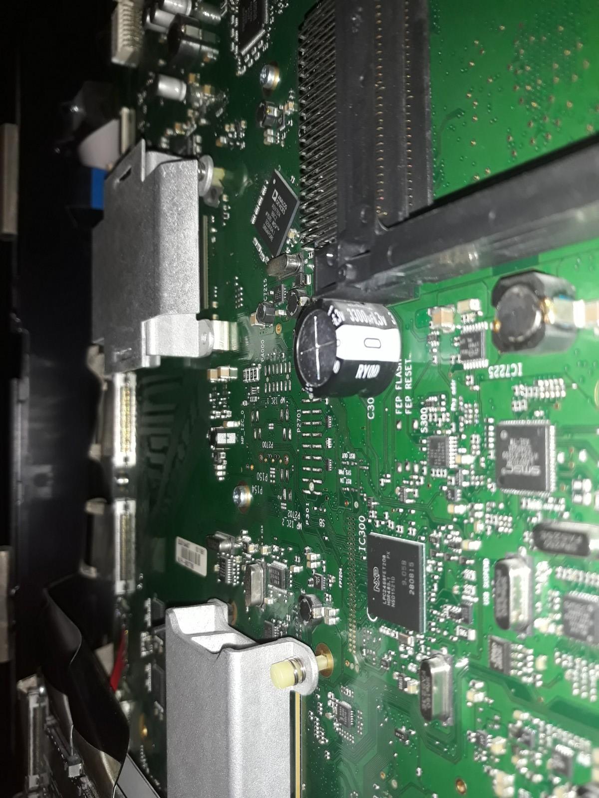
          These are photos from Avant 75.

          Avant75_1Avant75_2

          in reply to: Beoplay V1 not turning on #55584
          jacek1313
          BRONZE Member
            • Topics Started 0
            • Total Posts 7

            This is the original capacitor from Beosystem 4.

            in reply to: Beoplay V1 not turning on #55580
            jacek1313
            BRONZE Member
              • Topics Started 0
              • Total Posts 7

              BeoSystem 4 boards already use a 3300uF capacitor.
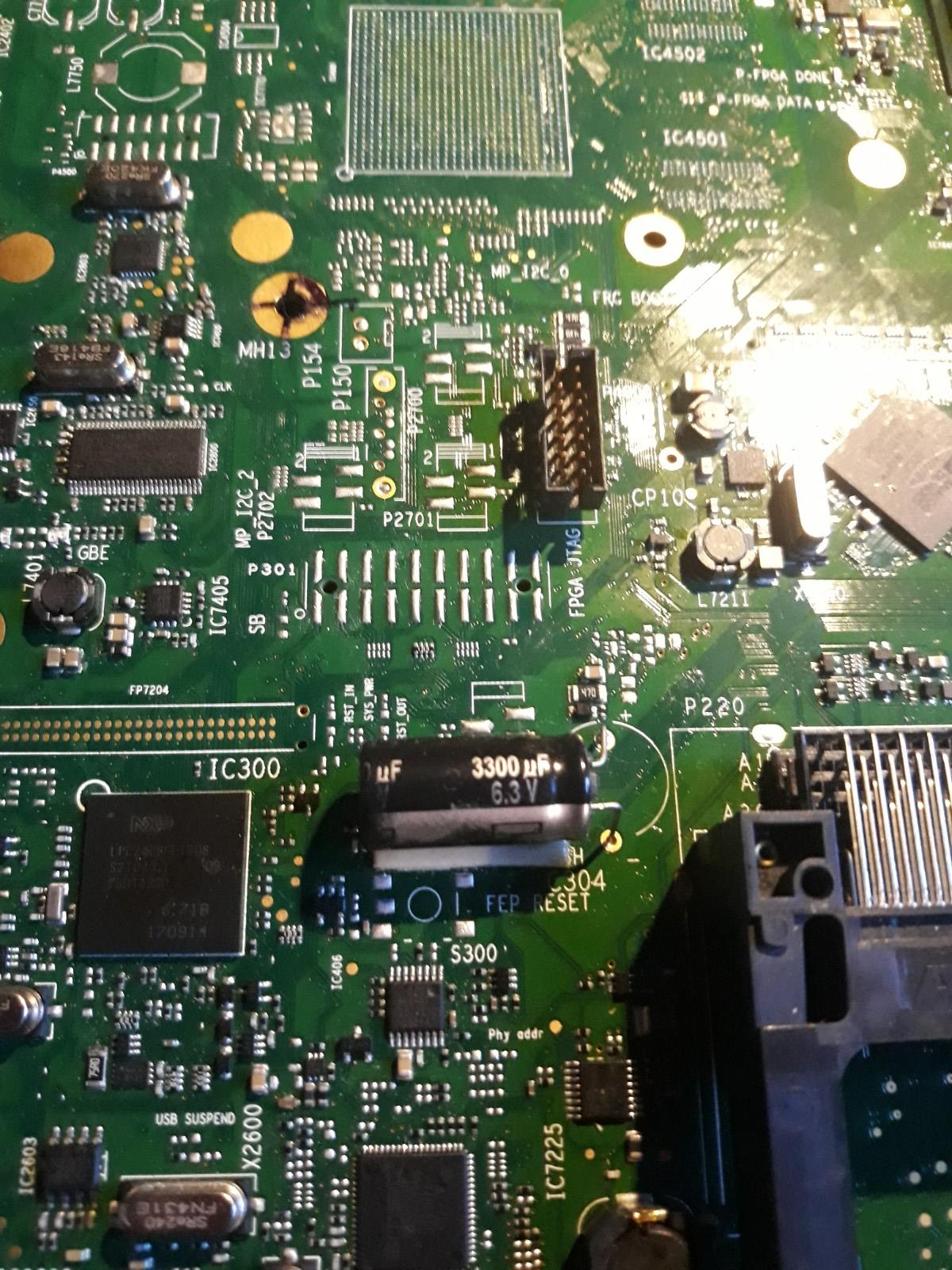
              BS4_C

              in reply to: Beoplay V1 not turning on #55574
              jacek1313
              BRONZE Member
                • Topics Started 0
                • Total Posts 7

                I don’t have any photos. I cleaned the PCB under the capacitor to bare copper, soldered the paths with thin wires and covered them with PVB varnish.

                in reply to: Beoplay V1 not turning on #55567
                jacek1313
                BRONZE Member
                  • Topics Started 0
                  • Total Posts 7

                  Hello, in my case the electrolyte from the damaged supercapacitor damaged the PCB paths that ran under it. I could barely solder them.
                  One of them is the signal from the IR module to the FEP IC300 processor.

                Viewing 7 posts - 1 through 7 (of 7 total)