Forum Replies Created
- AuthorPosts
-
That’s just the handset and charger so you’ll need to add a PSTN in order to connect to the phone line.
Have a read of this FAQ to work out which one to get: https://beoworld.dev.idslogic.net/faq_view.asp?id=74
PS: And welcome to the Forum!! ?
Great. Be sure to come back and tell us how it works!
Guy, I’ve managed to create the Powerlink switch functionality like this
I don’t fully understand the technical aspects, but I don’t think it’s a good idea to have such a setup. Even if only one of the devices is powered up, the output stage of the ‘dormant’ device is effectively connected in parallel with the output of the ‘live’ device. In extremis this may cause damage – I think it’s something to do with output/input impedance and the dangers of overloading the source (or Beolabs, or dormant device). Be careful!
The cable Steve mentioned was to connect the Core to the Tape input. I suppose this will work from Line Out to the core.
Oh yes – the cable in his first link was indeed RJ45 (Core Output) to DIN (BM7000 tape input). This will not work as a Line Out to the core.
But I think the best option will be the Powerlink switch
Agreed!!
Guy, you are a legend for showing me that website!
Very happy to help!
The real question is what cable do I need to use the Line Out from the BM7000 to Core 3.5 mini jack?…
Steve’s already linked to a suitable cable that he can supply but his shop is closed at the moment. I have a quick look for an alternative supplier but it is difficult to guarantee that the cable supplied connects to pins 1 and 4 (i.e the output pins) of the BM7000’s DIN sockets.
One solution I have used in the past is to purchase one of these: https://www.amazon.co.uk/Phono-Cassette-Interconnect-Cable-CoolNovelties-Black/dp/B016CAJSSG/ref=sr_1_4?crid=2GD3UJUHDE665
This cable connects to both input (one pair of RCAs) and output (the other pair) of the 5-pin DIN.
You can then add something like this: https://www.amazon.co.uk/3-5mm-Female-Stereo-Adapter-0-20cm/dp/B09SM5LQT3/ref=sr_1_14?crid=1S3XMO47QSXEF to connect the appropriate RCA pair to the Core’s line-in.
Doesn’t Almando do something like this?
Yes but it’s a bit more pricey – possibly because it has extra functions that you don’t need in this application.
I haven’t used either specific product, but have purchased other OneRemote products in the past and been impressed.
Hi Kiran,
If you still want to avoid the double-volume issue then you could still use the BM7000’s Line-Out. This shouldn’t effect use of tape; both Tape 1 and Tape 2 DIN sockets should provide input and output at the same time.
However, there is another way of looking at this. You effectively have two B&O devices sharing one ‘set’ of Powerlink speakers. That is exactly what this device is designed for: https://shop.oneremote.dk/shop/69067-powerlink-switch/4162-powerlink-speaker-switch/
Have a look at this thread: https://archivedforum2.beoworld.ouronlineserver.com/forums/p/3595/32375.aspx#32375
Although the images do not currently appear, if you click on them and then amend the start of the ip address from ‘forum’ to ‘archivedforum2’ they will appear!
And the B&O part numbers:
(Click on images to enlarge and add clarity)

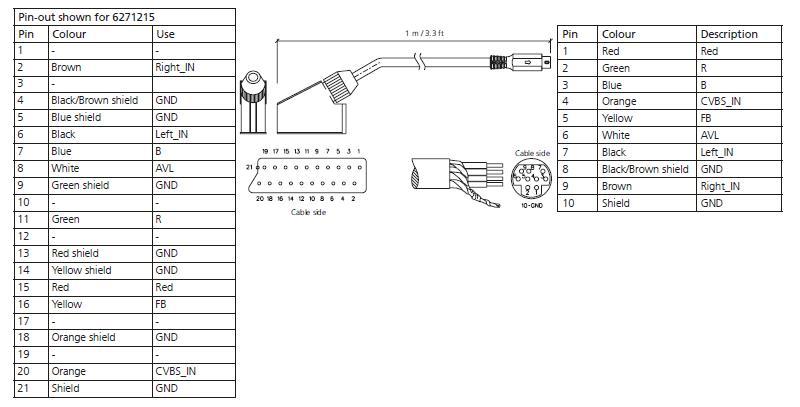
Here’s the full pinout diagram. For some reason I couldn’t take a pdf snapshot yesterday!

I’m only getting an audio signal to the Core using the Powerlink connection
This is because PowerLink uses pins 3 and 5 for audio output, whereas DIN Aux outputs use pins 1 and 4. You need a different cable.
Not to mention, how else to record the “FM-Simulcast” onto the “VCR” audio track?
I made my edit as you were posting – great minds think alike!
Of the BM7000’s DIN sockets, TV/AUX, TAPE 1 and TAPE 2 are all fully-wired hence can provide AUX output – how else could you do tape-to-tape recordings*? ?
Only CD and PHONO are input only.
EDIT: Not forgetting of course the ability of the VX7000 VCR (connected via TV/AUX and a suitable Beovision) to record/playback up to 8 hours of ‘hifi’ audio using an E-240 VHS cassette in LP mode! Life was much simpler then …
Here’s the full pinout diagram. For some reason I couldn’t take a pdf snapshot yesterday!

I was just thinking about this further and reckon that the SCART connections in the diagram are wrong. As far as I know, SCART audio out is pins 1 and 3 (not 2 and 6) and composite video out is pin 19 (not 20). Hence I would hope that B&O’s cable would have the Brown, Black and Orange cables to SCART pins 1,3 and 19 respectively.
EDIT: I just worked out the anomaly! The diagram says ‘Pinout shown for 6271215’ which of course is B&O’s cable with a female SCART socket. Hence connecting a further male to male SCART into the device would ‘correct’ the connections from input to output. I can relax now! ?
Have a look at this thread: https://archivedforum2.beoworld.ouronlineserver.com/forums/p/8855/78144.aspx#78144
The AV signal will be one-way (into the TV), but the second-to-last post suggests that you may be able to control the B&O devices (if AVL means datalink in this context*)
* EDIT: I had a look at the SCART to mini-AV pinout connections in the Beolink Handbook v1.9 (page 128) and it shows that SCART pin 8 (which is used for datalink) is mapped across to mini-AV pin 6 and is also labeled as AVL. The part number of the official B&O cable (3m version) is 6271217 D.
Does anyone know what could be wrong here ?
The cable could be wired for the signal to go in the opposite direction. Have a look at the diagrams here – schematics 7 and 8 may explain the problem (albeit you need to imagine a female DIN): http://www.hifi4all.dk/forum/forum_posts.asp?TID=32157&PN=1
EDIT: The cable that you have bought is for an input into a DIN-equipped B&O amplifier – hence wrong direction. You need one like this: https://soundsheavenly.com/beogram-record-players/14-2244-beogram-to-non-bo-device-phono-pre-amp-receiver-amplifier-etc.html#/2-length-1m/60-grounding-internal_ground_link
With a BeoMaster with built in pre-amp (some BeoMaster 4500s have that), you could skip a box (I am not sure if more recent BeoSounds that have a MasterLink connection can control BeoGrams through their AUX sockets). It will also require some persistence to program the BLC. But unless I oversee something I believe it could work.
As far as I know only the Ouverture (Beosound 4000) has both datalink and masterlink. But of course the Ouverture has no RIAA amplifier (which the 8002 needs). If using a separate RIAA amp you would need to be sure that the datalink signal is passed to the correct datalink pin, as explained in this thread (see post by joeyboygolf): https://archivedforum.beoworld.org/forums/t/41586.aspx
Hi Fabiqula,
It’s probably better to ‘bump’ (or just re-post) in your previous thread on this topic rather than starting another thread. This just helps to keep the forum tidy!
Regards Guy
(If you do re-post there I will delete this thread)
Further to Nanoloop’s comment below – I believe that you will need the slightly thicker fully wired Mk2 version of the Powerlink cable in order to ensure correct on/off and muting function.
Here’s an example as supplied by the site sponsor: https://soundsheavenly.com/powerlink-8-pin-din-connection/23-319-powerlink-mk-2-compatible-black-8-pin-din-cable-with-fully-wired-8-cores.html
It’s worth checking with Steve that the Mk2 is correct – I am 99% sure ?
(EDIT: Make sure that your disconnect the ML cable as it is not necessary in your configuration, and will probably stop the Passive from working correctly. The Passive’s ML input is for the situation when it is powering speakers in a Link Room away from the main system, and in such a setup it would need the IR eye also.)
does that mean you can use MCL IR sensors (square ones) with more modern hardware that need round sensors ?
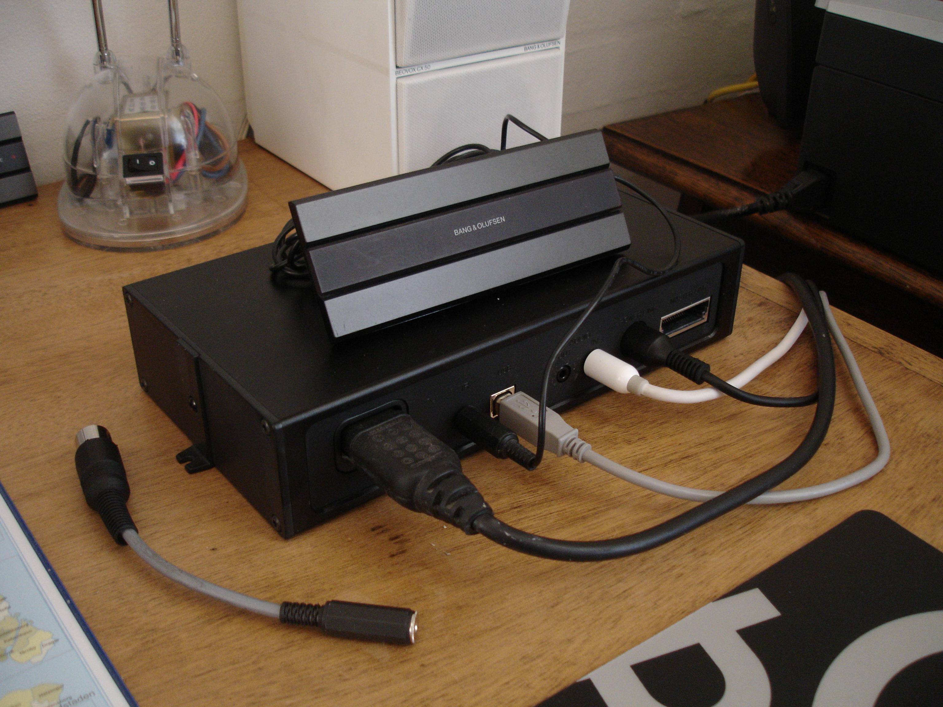
I definitely used an old VX sensor as the IR input for a Beoport, and I remember making a short adaptor so that I could also connect it to a Beolink Passive or Active – see photo (adaptor lying on desk to the left):

But I have never owned any of the older MCL82 equipment hence can’t comment. However, if you can determine the correct +ve, ground and ‘IR data’ connections in the MCL82 sensor (and if it also runs on a 5V supply) then it would be worth a try to see it it works as an IR sensor for newer equipment.
I may have posted more about IR sensors in the archived forum – hopefully it will be back soon!
- AuthorPosts
