Forum Replies Created
- AuthorPosts
-
Part of my reasoning for running the calibration process is that it is a quick way to test that the BC9000 is recording. It provides a test recording that is tolerant to any head alignment problems since recording and playback are done at the exact same head azimuth angle. This test also excludes some of the line-level circuitry that I’m not trying to test yet.
The newly recorded test tones play reasonably load and clear on other tape decks. I don’t know exactly what they should sound like on other equipment or have any quantitative measure of the record levels since my other playback devices don’t have any meters. This might all be a moot point since I’m not trying to address any record issues right now. Everything that I’ve tried so far indicate that recording is generally working OK.
During the calibration test I expected to see record levels around 0dB +- 1 or 2dB. The BC9000’s PPM was just barely hitting -8dB. I generally believe what I am seeing on the PPM since it is consistent with what I’m hearing at the headphone output. I’m not having much luck probing the signals that I have since the signals are so small and connecting test equipment pulls them down even further. This is one area where hearing about any tricks for testing or expected behavior would be appreciated.
The circuit path that I’m concentrating on is from the tapehead to the headphone output. This includes the fewest number of stages (i.e. the simplest test scenario).
Tapehead -> JFET stage -> IC8 opamp stage -> BJT transistor stage on board 4 -> BJT transistor stage on board 2 -> (part of) Dolby chip stage -> headphone amp or PPM
The only stage that I’ve ruled out is the headphone/PPM stages, mostly because they corroborate each other both on tape playback and with the “injected noise” when I touch the board 2 signal inputs.
I am trying to be cautious with any experiments that I try to minimize losing or messing up any of the factory calibration settings. My access to the “test tapes” mentioned in the service manual is limited to the “azimuth tape” that was included with the BC9000. I’m also assuming that the AF meter mentioned in the service manual is an analog meter. Advice on testing with more modern digital instruments would also be appreciated. I really don’t know what is truly important to get perfect versus where “close enough” will work.
Glitch
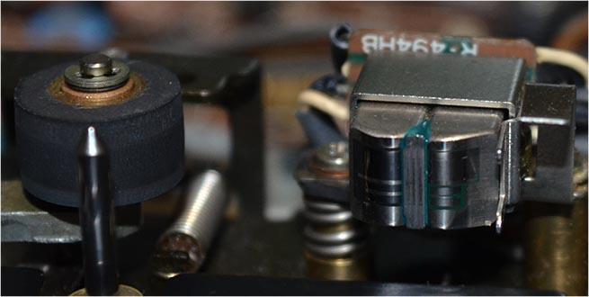
Here is a picture of the tape head
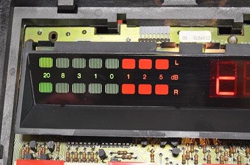
And the meter during playback. The left channel is “stronger” than the right, but neither gets significantly above -20dB.
Glitch
Mark-sf: The tape heads are clean and have very little wear. I haven’t tried to do any tapehead adjustment/alignment since the signal level is so low that I wouldn’t trust the readings. I don’t have any reason to believe that the tape head is out of alignment.
I did take some measurements of the playback head itself.
Channel1 212 mH @1kHz 487 ohm @1kHz 430 ohm @DC
Channel2 215 mH @1kHz 521 ohm @1kHz 433 ohm @DC
I don’t know what the exact readings should be, but the values seem reasonable.
Martin: I see the same symptoms (levels not greater than -20dB) with tapes recorded (years ago) on this BC9000 and prerecorded tapes. The same tapes play normally in other tape players.
I’ve also tried to go through a record calibration process. The calibration does not succeed, but when I play back the section of tape where the calibration tones were recorded I get the same -20dB signals.
I tried swapping out the IC8 opamp with a known working one that came out of my upgraded Pentas. This didn’t make any difference.
Also, when I touch the input connections to the Dolby board, I see a jump in the meters up to about -3dB. I assume that this indicates that the Dolby chips are alive.
My current thoughts are that the problem is in the JFET and trim-pot R148/R248 stage. Does this make sense?
Glitch
I found a short to the metal chassis of the tape transport. It looks like when I plugged-in B6-P19 it made a connection to the chassis via the tape head mount, to the tape head angle adjusting spring, to the tape head sliding bracket, to the transport chassis. This unlikely, and easily opened, connection likely explains why I didn’t catch the short when I checked continuity between all the pins on the 14 and 16 pin connectors and the ground pin on B6-P19.
Glitch
alf: Are your startup issues resolved? If not, I’ll have one of my BM8000’s on the bench within a few weeks for a full recap. I can capture some scope traces of the start-up procedure if you think that it would help you. Let me know.
One thing that I noticed about the BM8000 is that the receiver is sensitive to startup conditions. Both of my BM8000’s start normally when plugged directly into an outlet. Neither of them will start when I run them connected with a light bulb (current limiter) in series.
Glitch
I’m also out of ideas of what to try relative to the CPU. I’ve been able to test (most of) the rest of the receiver and aside from a few LEDs being dead, it still works pretty well. It has been a long time since I’ve listened to this piece of equipment. I forgot how nice it sounds, with a smooth, mellow quality that is hard to describe.
Can anyone comment on the availability of replacement CPUs?
My assumption is that they are generally unobtainable and the best bet is picking up a microprocessor board from a unit that is being parted out (that may or may not have a similar problem).
I have tried running this latest set of tests both with and without the crystal. I removed the crystal and capacitor from the BM6000 board and used this for the external test. I have some reservations about running this in a breadboard setup, but it is what it is.
My logic may be flawed, but running without the crystal should give an indication of how the I/O initializes from purely a electrical circuit standpoint. With the crystal, I would expect to get an indication of what the software is doing. I don’t really know what happens in the grey area in-between the two, or if there is a grey area. My recollection is that microprocessors of this era just started running whatever op codes were stored at address 0x0000 when powered on.
In the traces posted earlier, the reset signal is simply tied to the power signal. I know that this is not the ideal situation. I would have rather been able to generate a delayed signal that was triggered from the power signal, but I don’t think that it is possible with the test equipment that I’m using. If the RESET signal looks early, it is likely an anomaly related to how the test equipment scans or displays the signal.
I did a quick test by manually changing the reset signal (plugging in a jumper on the breadboard).

Except for the FreqCount signal, all of the signals usually remained unchanged. The FreqCount typically goes high for a random period of time, then returns to zero. I’m not sure what to surmise from this behavior.
I expected to see the outputs update as a group (of 8), but not all of the bits being the same value. For example, in the Data Strobe set of signals, I expected to see something other than 0 or 7 (all zeros or ones), which would indicate that the software was polling the keyboard or setting a particular LED display.
I don’t have any real experience with trying to debug a faulty CPU. Typically, at work, if a circuit/CPU was acting flaky, we trashed it and replaced it with a new one, or sent it back to the hardware group that likely did the same.
I didn’t expect my bench test to produce the behavior of a properly functioning CPU in a BM6000. It would be a very difficult to replicate the exact timing of all of the signals such that the diagnostics were happy. I did expect that the results from a given test would be fairly repeatable.
It seems like the CPU is running random assembly code. So far, it has not hit a HCF opcode, but it feels like it is just a matter of time ;-).
Glitch
Thank you for the link to the BeoMicro webpage. I’ve read a few of the pages so far and find the site very interesting. I expect that I’ll eventually read the entire site.
Regarding the BM6000 start-up, what the pins do at start-up may depend on how the CPU was configured when ordered. There were multiple options as shown in the diagram below from the CPU data sheet. Interestingly, on the Appendix 9 page of the BeoMicro site, the engineer comments on this topic.
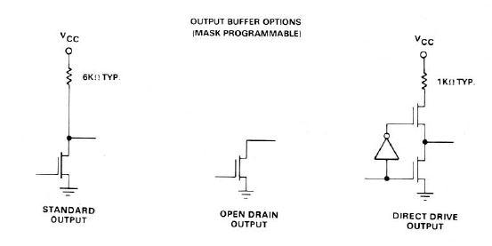
I assume that CPU was configured with the standard or direct-drive output due to lack of external pull-up resistors (needed for the open drains) on the BM6000 board.
At this point in time, I’m just trying to figure out if I have a functional CPU versus a working CPU that is being faulted by something not working right on the board.
My latest experiment is to run the CPU on its own connected to a logic analyzer to see if I can learn anything from how the signals initialize or change. I would expect that direct-drive outputs controlled by the assembly code to behave slightly different than standard outputs. I may not learn anything from the experiment, but I’m not sure what else to try.
Glitch
I think I’ve been able to convince myself that the CPU is bad. I ran the logic analyzer test and the results were inconsistent. I expected that with a clean and simple test setup that the CPU behavior would be very repeatable. It wasn’t.
Below are a few scope captures with just power and ground connected and the various outputs monitored. The capture was triggered on the 5v power signal rising.
Most of the time I saw this…

However, other times I saw different behavior


The only consistent thing I noted was, at some (random) time, all of the signals would simultaneously go to zero.
I repeated the test with a 50/60 and TimeBase signals provided by a waveform generator. These results were also inconsistent.


I saw many other signal combinations. The only trends noted were that signals would not change after some (random) period of time and the outputs seemed to change in groups of four.
I also ran some traces to see if I could identify the output configuration type.

I think this plot tells me that the outputs are the direct output type and initialized by the software. I would expect the standard output type to all initialize simultaneously with the power signal.
Unless I get any more suggestions, I will give up on the CPU and move on to “plan B” for the BM6000
Thanks again to all that provided suggestions,
Glitch
I haven’t been paying attention to anything related to vinyl for over 25 years and have no idea of how the technology progressed. I was hoping that sometime in the past a company made MMC compatible cartridges that were very unpopular and could be picked up cheaply on the used market. This was wishful thinking on my part.
I think my Beogram is in pretty good shape considering that it hasn’t been used for a few decades. The first thing I did was remove the MMC1 and place it in its original case. I’ve spun the platter with the “turn” function, changed speeds with the speed presets and with the +- buttons. I’ve moved the carriage with the “<< <” and “> >>” buttons and it works smoothly. Hitting play without a record on the platter correctly detects the absence of the record. It also seems to be communicate properly with the Beomaster. The only possible issue that I’ve noted is the speed indicators sometimes blink. I don’t know if this is an actual speed mismatch problem or just the turntable’s way of warning me that there is no cartridge or record detected.
I’m hopeful that the restoration is as simple as replacing the belt and caps. My concern about the cartridge is related to the machine doing something unexpected, like dropping the cartridge hard, due to something like a broken solder joint or other loose connection. It is hard to predict what could happen due to servicing. I’d rather risk a cheap or $200 cartridge than my MMC1. To me, a lot of the value of my own MMC1 is that I know the provenance of it.
I’m probably worrying about nothing. My Beogram has been one of the most trouble free pieces of audio equipment that I’ve owned.
Glitch
Martin,
Thank you for the information. The list of parts that changed between the two versions is helpful to know in case I ever need to swap boards between the receivers for debugging. I assume that swapping is still possible, but the results might be confusing due to mismatched displays. Hopefully, I’ll never need to try this.
I was trying to get a rough idea of what year each of my receivers was built. I know that my newer BM8000 was very late in the production cycle since it was purchased in 02/1986. I have very little information about the other one since I bought it used.
I’ve done a quick search for B&O serial number decoders, but none of the information makes sense for the serial numbers that I have.
Glitch
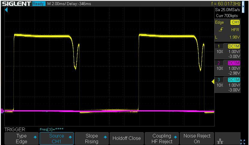
I cleaned-up the “blip” enough that it should be considered high from a TTL point of view. This didn’t appear to make any difference in the overall power-up issue.
artig,
Thanks for the suggestion.
I checked the 50-60Hz signal fairly early in the debugging process. I saved a trace of the signal as a reminder to investigate an anomaly in the signal.
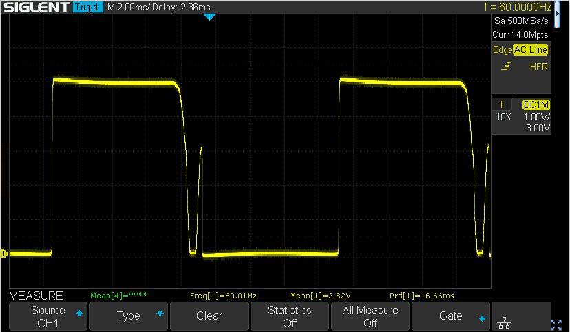
The extra blip in the signal is unexpected. My assumption was that the 50-60 signal would just be used for the timer functions and I would revisit this signal if the timers had issues.
I rechecked the 50-60 signal today and (initially) the signal constantly stayed low. I started to debug this and it “spontaneously” started to work again.
I ran an experiment where I decoupled the power supply (PS) from the CPU board by removing the pin P47-1 from the PS connector. I added a 10K pull-up resistor on the P47-1 connector side so I could check the PS circuitry. The PS circuit worked as expected except for the extra blip. I also monitored pin16 on the CPU. Sometimes pin16 would stay low, other times it would go high. The state of the signal seemed consistent with what was showing on the display. If the display got stuck at “:.” the signal seem to stay low. If the signal got to the “.” (standby?) display, the signal stayed high.
My interpretation is that pin16 on the CPU is pulled high as part of the CPU start-up process. However, I am having a difficult time determining if this is part of the CPU hardware initialization (standard output per the MK3870 datasheet) or if the software is controlling the pin state (direct output). This would only matter as a way of determining if the CPU is running. Pulling pin16 high makes the 50-60 signal “active” and the transistor circuit on the power supply will pull it low at at the appropriate time to make the 60Hz square(ish) wave. The CPU can then read the signal as needed.
I’m also trying to understand if the controller is faulted because the various signals are bad, or if the various signals are bad because the controller has faulted.
As a long-shot, I’ll try to get rid of the extra blip and see if that helps.
It would be interesting to see the source code for this. Then again, it is likely written in assembler and figuring out how it works would be a headache.
Glitch
I haven’t made any real progress on the BM6000. I’ve resorted to replacing diodes and transistors that I didn’t think were bad. The removed parts tested OK. I’ve been able to slightly change how the circuit reacts, but it is just a different version of random behavior.
The good news is that I’ve been able to get my Beomaster 8000’s working. I have one fully working and a second that works except for the FM display. I have parts on order to fully restore/repair these.
My next step on the BM6000 project is to run some experiments on one of the BM8000’s to see if I can learn anything about how B&O handles the start-up procedure, especially when faults are detected. Ideally, I would run these tests on a working BM6000, but since I don’t have one, I’ll have to make due with the BM8000.
I’ll keep monitoring this tread to see if anyone has suggestions on things to try and report if I make any progress.
Glitch
I like the idea of the broken turntable with a good cartridge. The downside to this is trying to explain this plan to my wife. The argument about selling the turntable wouldn’t carry much weight since my “buy-to-sell ratio” is overwhelmingly weighted towards “buy”. Also, she seems to prefer things in small packages even if they aren’t for her ;-).
Glitch
Mark: Thank you for the suggestions. I’ve started watching eBay for used B&O MMC’s. I looked at the Sound-Smith website and the SMMC4 seems like it would be a good candidate (and likely what I’ll get). However, it is at a price point where I’ll have a hard time justifying the purchase to my wife. I’ll also keep my eye out for a used SMMC4.
Guy: I’m in the USA so the duty and shipping won’t be an issue.
Are B&O and Sound-Smith the only sources of compatible cartridges? I suspect that other sources are unlikely, but wanted to ask to be sure.
Thanks,
Glitch
Christian,
Your reply above is consistent with what I’ve read about the B&O equipment of this era. B&O was pushing the bleeding edge at the time and reliability sometimes suffered as a result.
I’m hoping that I can get my BM6000 to show enough signs of life that it is worthwhile to spend the time and money to do a full restoration. I’m still hoping that the issue is related to an overly sensitive startup procedure and it is just a matter of figuring out what it takes to make the CPU happy enough to keep running.
Thanks again for your help,
Glitch
Christian,
Thank you for the reply.
I just rechecked the STROBE (Digit Select) signals on pins 26-28. All three signals are always HIGH (+5v). The only time that they change is when I plug or unplug the receiver.
I’ve checked these in the past and expected to see them changing. My assumption is that all HIGH on these signals means that the display is either meant to be blank or that the CPU is not properly updating the signals. Since some of the other signals that I expect to change during power-up are not changing, like the RELAY signal, my theory is that the CPU isn’t running properly.
I think that the STROBE signals and the downstream circuitry is not broken since I was able to get the “P” display, as well as other LEDs randomly lit, when I ran the microprocessor board outside of the chassis with bench power supplies.
My interpretation of what I’m observing is that the CPU initially starts, then fails or stops at random times. What I see on the displays and other signals depends on how long the CPU runs before it has an issue. Of course, I might be having tunnel vision on this theory and would be happy to try alternative solutions.
What did you do to fix your STROBE issue on your BM8000?
Glitch
- AuthorPosts
