Forum Replies Created
- AuthorPosts
-
The red cap – you mean the polyester cap? It’s not polarised so it doesn’t matter how you put it in. Can we see the back of the board also?
I don’t understand the part about: “The player started OK but when I moved it to the amp it did not read the cd anymore.” Do you mean that it played okay on your work desk when it was assembled? You then physically moved the unit, hooked it up to the amplifier, and then it didn’t work?
Strange that we would only get the normal/standard VHS version in Denmark/Europe – but perhaps it was because S-VHS never really took off here.
C2103 was changed? Looks pretty old and original to me. I changed mine to a blue Philips type 47uf/40V.
Maybe a picutre of the board after modification would help.
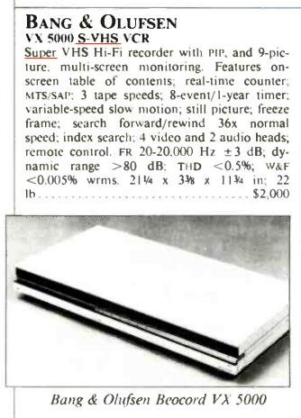
Was the VX 5000 available as S-VHS in the US?
I have seen multiple pictures online sporting the S-VHS logo and also this ‘review’ from Hi-Fi Stereo Review mentioned it is S-VHS.
In the manual for the 7-4 it says to use a specific type of Powerlink cable as others can cause hum.
I picked up at VX5000 for free yesterday.
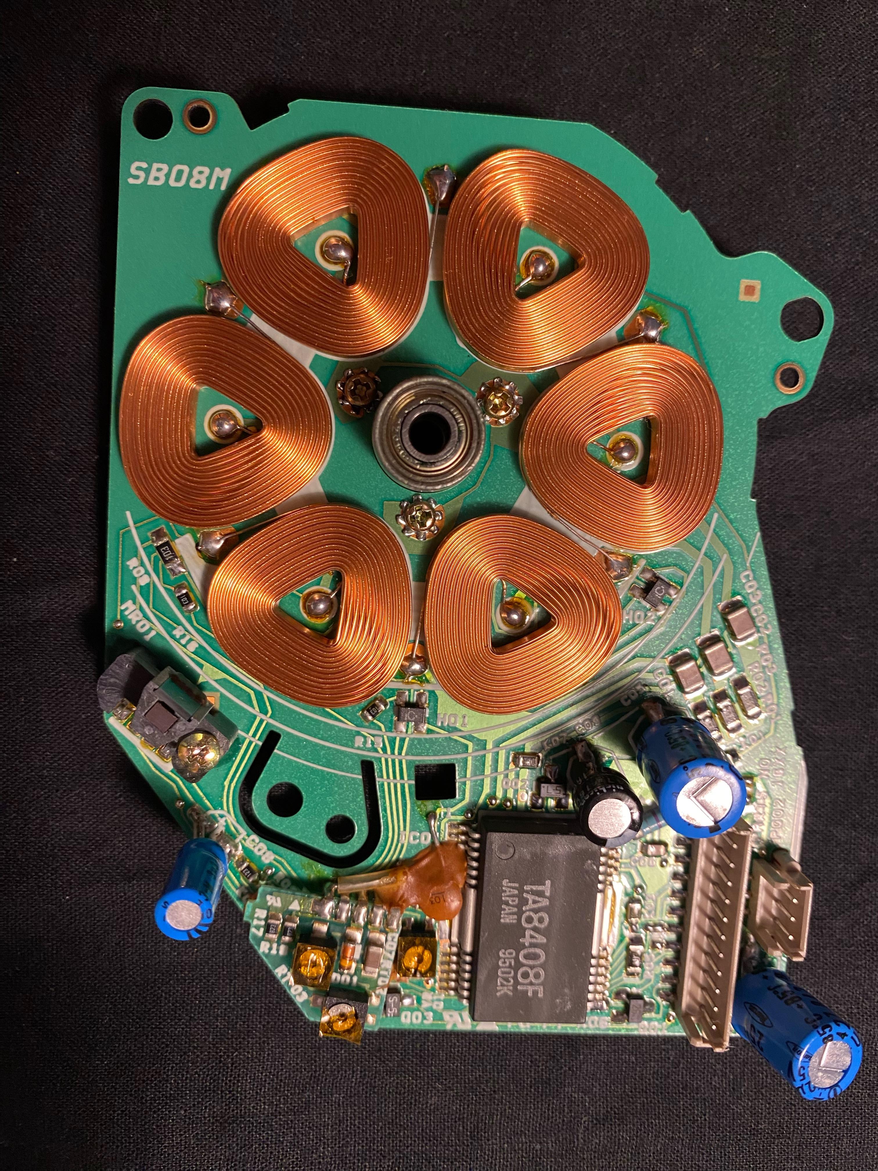
Opened the bottom, and the belt had turned to black goo. Cleaned it up, ordered a new belt, and changed 4 SMD caps on the capstand motor board. All of them had leaked but there were no damages to the board. I then turned the VCR on briefly, and it was alive. I quickly turned it off again as not to ruin anything, and as I still need the belt, and some cables to actually be able to see if the video works. I don’t really plan to used the VCR but it has a nice design. All it is missing is the front panel that covers the buttons.
Belt had turned to black goo:
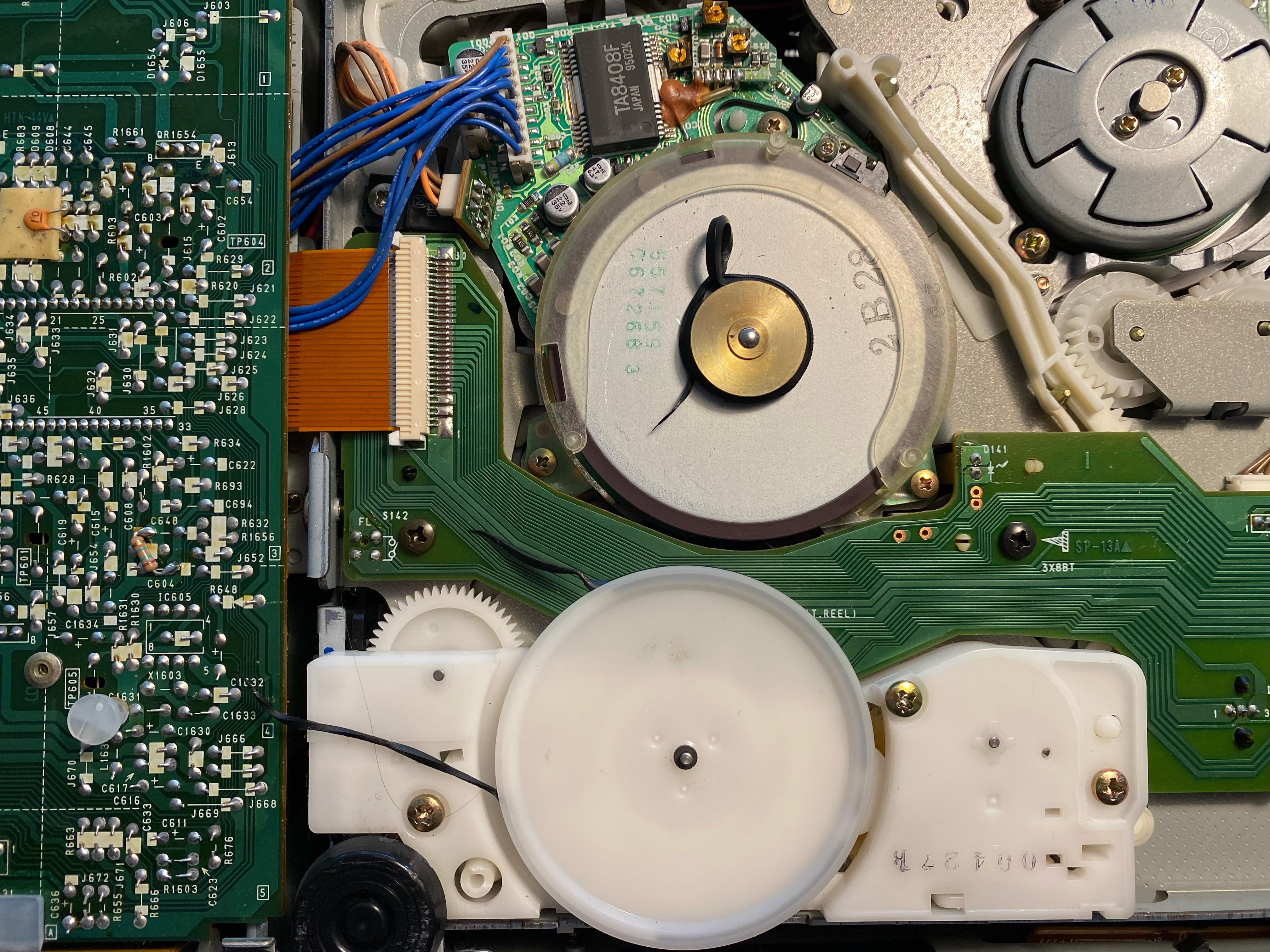
Capstan board with four SMDs that needed a change:
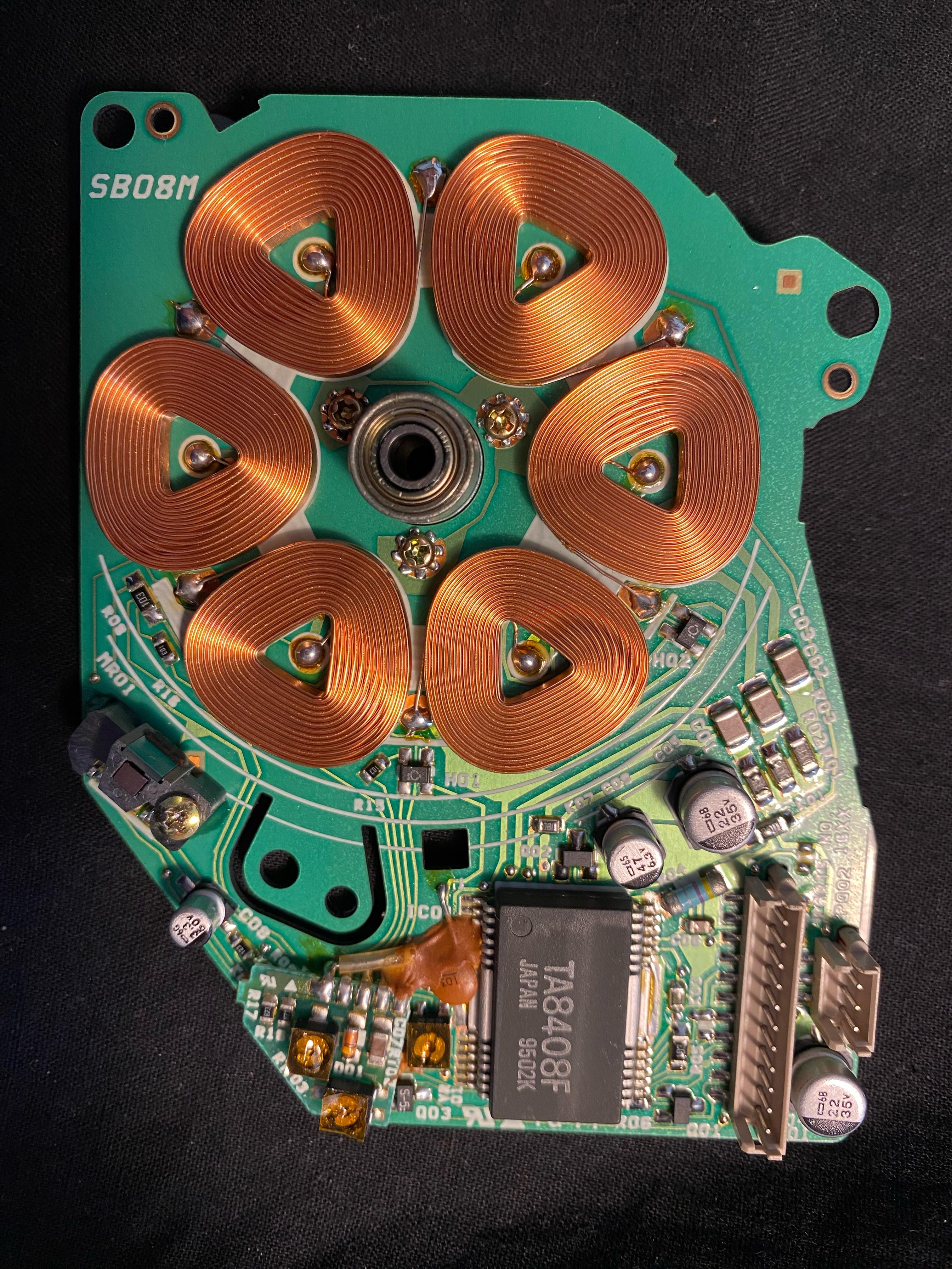
Can you spot the leakage from the SMDs?
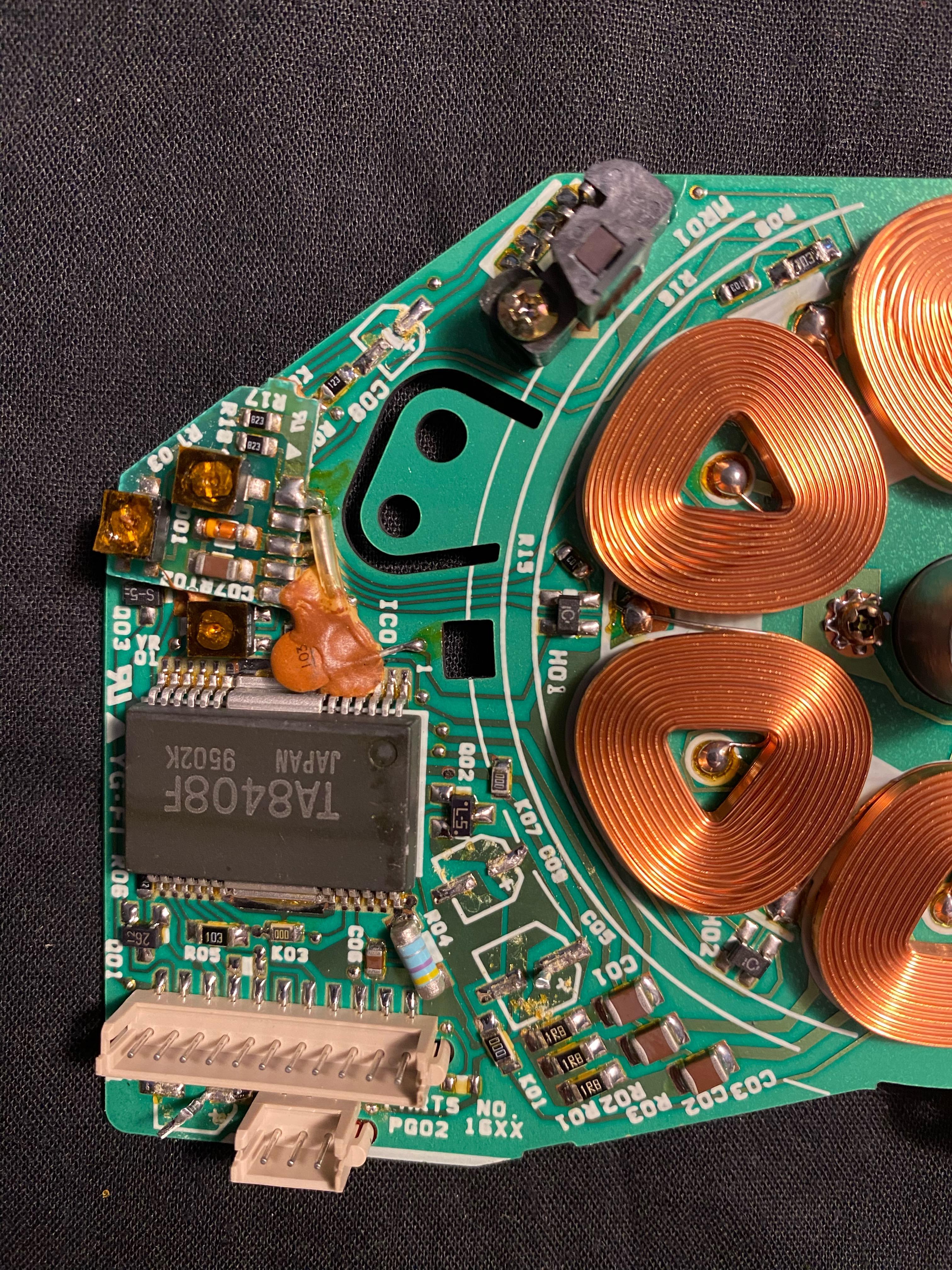
The capstand board after replacement of capacitors. My local caps pusher only had Philips and Nichicon caps in these sizes:
Nice!
If I read the schematics correctly, the fault could be between 1TR2 and 1TR3. So start by testing those two transistors.
C2103 is the one all important capacitor to change. Search on the forum and you will get a lot of hits. There could be others but I would start with this one. Since I changed it in my Beogram 7000 CD player, it plays absolutely everything. Before the change, it was very picky about which CDs it would play.
D10 and R18 on the powerboard, not the computer board. On the computerboard the F 1A fuse blows, so will have to restore the proper voltage rails first.
I will need to do some more measurements when I have time. Thank you for the help so far.
D10 was indeed not working. Also R18 was defective. After replacing these two, I now have +40V back on p14-6. Yay. A small victory.
There are still some problems though. On P18-5 I now don’t have -40V – I have no idea why as it worked before. And none of the voltages on P15 are correct, so I don’t have 28V on p15-6, I don’t have 12V on P15-3, and I don’t have -12V on P15-2. Sigh. P24 also still gives around 5V instead of the specified 11V.
Die Bogener – I love your pictures – but when I press them, they never zoom in; they always take me to pic-upload.de 🙁
When in Auto mode, it will only move the upper panel down when you lift it up from the table. If you want it to lie straight on the table you must do it manually.
Can you run the VTR without a cassette? See section 7-1 in the service manual.
Also, if the fan motor is blocked, the VTR goes into standby within 1-2 seconds according to the service manual.
Did you clean the black part with the white pin with an arrow in the middle – not sure what it is called – to the left of the drawer motor. It will corrode and could cause all sorts of problems.
This thread by Die Bogener is also worth a read.
Looks like D10 is shorted. Will change it.
Finally had some time to look again, and also I understand the schematics a bit better now.
Checking the voltages on board P9. On pin 3 there should be 40V but I measure around 26V – it drops ever so slightly and keeps dropping until 25.87V when I measure with the multimeter. 40V is supposed to come from 2P14-6.
On board 2 P14, pin 6 gives me also around 26V – logically. Seems like it passes through C10 which I did not change – it measures 57uf capacitance and should be 47 – so I guess it is slightly out of spec – could that be the issue?. P18 measures the specified -40V.
On board 2 P24 should give me 11V but it gives around 5V.
Any help is appreciated.
Keine Ursache. Du brauchst 2 Powerlinkkabel (die hast du schon), und 2 Stromkabel (davon hast du schon einen). Also brauchst du eigentlich nur einen Stromkabel (Euro 8-Form) zu kaufen, oder du hast einen übrig von einem anderen Produkt, den du verwendet kannst.
- AuthorPosts
