- This topic has 5 replies, 3 voices, and was last updated 2 years, 4 months ago by
Mark-sf.
- AuthorPosts
- 16 October 2022 at 09:30 #39893
Hej everyone,
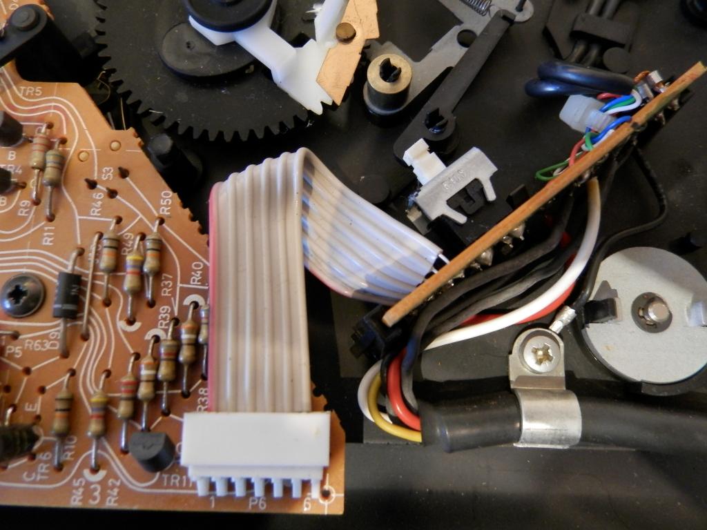
My Beogram 5005 had started to behave a bit erratic (weird shut-off loops etc) so I decide to see if I can fix it. I open it up to find that on the Control Board the main capacitor (C2: 470uF/16V) had blown and a few resistors overheated, most likely causing damage to other components. Being that these parts are close to 40 years old and it would be fun to work on my soldering skills, I’ve decided to replace all the components and keep my old record player alive.
I begin checking all the resistor bands to list what parts I need to purchase, but didn’t know what Power Rating the resistors needed to be. I checked the service manual, it only specifies Power Rating for 4 unique resistors to the Beogram 59XX and the rest are stated as “Standard Resistors”, categorised in resistor value tables matched to B&O part numbers, not the wiring diagram.
Can anyone point me in the right direction to figure out the which Power Ratings for the resistors I need to purchase? Or maybe even better, are there complete component kits available?
Thanks for any help,
17 October 2022 at 02:57 #39897Well I found out the problem, I simply forgot to adjust the unit scale on the multi-meter. I’m questioning my right to exist right now, but you live and learn I suppose.
Only a handful of resistors were out of spec, but most likely fine, I’ll change the catalytic capacitor (C28), some diodes that are showing resistance both directions and test the system again.
Thanks for your time and patience, I’ll get parts later this week so hopefully I can get it working soon.
17 October 2022 at 05:36 #39898Diodes like transistors typically cannot be measured without being removed as you are measuring resistance of their circuit.
17 October 2022 at 08:26 #39895If you are referring to the resisters in the lower right where the board is darkened, those are 1/4w resistors which are typically 6.5mm in length.
Thanks, I need the Power Rating for all through-hole resistors, is it safe to assume that all 6.5mm resistors are 1/4W?
I would check their values with a meter as even though the board is discolored most are probably fine when the resistor itself is not blackened in the middle.
I have done some measurements and the resistors connected to C2 (the blown cap) are dead and a vast majority on the board are out of spec (or dead). Please note, on that picture I have already replaced C2 which made the record player work fine for about an hour before the controls really didn’t work and it got stuck in a shut-down loop.
Also another question, should I replace 5% tolerance with 1% tolerance resistors? Any benefits or is it better to stay with the original spec?
17 October 2022 at 08:39 #3989617 October 2022 at 12:45 #39894If you are referring to the resisters in the lower right where the board is darkened, those are 1/4w resistors which are typically 6.5mm in length. You will not find a replacement parts kit that includes standard resistors. I would check their values with a meter as even though the board is discolored most are probably fine when the resistor itself is not blackened in the middle.
- AuthorPosts
- You must be logged in to reply to this topic.


