- This topic has 6 replies, 4 voices, and was last updated 1 year, 1 month ago by
markg2000.
- AuthorPosts
- 12 January 2024 at 01:16 #52099
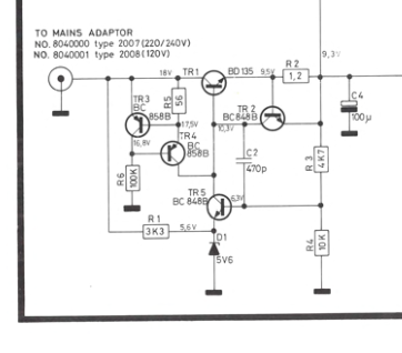
An archived post indicates that the center pin on the 12v DC input for the MCL 2 Expander is NEGATIVE. Can anyone else confirm this with absolute certainty?
12 January 2024 at 03:59 #52101Thank you, Madskp for confirming the center pin has negative polarity. I located the original 12-volt power supply that was used with this system for the last 25+ years. A multimeter reading does indeed show negative polarity (the DC output voltage on the old unit is now indicating 19-volts, hence the need for the new 12v DC power supply).
12 January 2024 at 05:34 #52102A multimeter reading does indeed show negative polarity (the DC output voltage on the old unit is now indicating 19-volts, hence the need for the new 12v DC power supply).
You might not need a new power supply. If the power supply is unregulated, it will read “high” if there is not a load applied. You might want to take the multimeter reading again with the either the device connected to the power supply or a dummy load that simulates the device load.
Glitch
12 January 2024 at 06:29 #52103A multimeter reading does indeed show negative polarity (the DC output voltage on the old unit is now indicating 19-volts, hence the need for the new 12v DC power supply).
You might not need a new power supply. If the power supply is unregulated, it will read “high” if there is not a load applied. You might want to take the multimeter reading again with the either the device connected to the power supply or a dummy load that simulates the device load. Glitch
I remember from another thread that the forum user GUY had the same experience with the power supply for a MCL2AV, where he meassured it at 20V even though it was rated for 15V
12 January 2024 at 07:01 #52104I remember from another thread that the forum user GUY had the same experience with the power supply for a MCL2AV, where he meassured it at 20V even though it was rated for 15V
Well remembered! I just found the post and I actually measured it at 23V. Worked fine though!
https://beoworld.dev.idslogic.net/forums/topic/mcl2-av-no-55v/#post-15498
12 January 2024 at 07:50 #52105In this instance I definitely needed a new power supply (see photo of the scorch mark on the MCL Expander board). This area was extremely hot when the old power supply was connected. I’m still trying to work through a problem of no LED lights and sound on the MCL boxes that are now attached a “certified-working” used MCL Expander box that just arrived from the UK (using the correct DC polarity from a new power adapter that was installed this morning).
12 January 2024 at 08:28 #52100An archived post indicates that the center pin on the 12v DC input for the MCL 2 Expander is NEGATIVE. Can anyone else confirm this with absolute certainty?
The diagram in the service manual also show this

I can confirm that my MCL2AV also has the center pin negative (even though the service manual diagram for that shows the opposite).
If you wan’t to be sure and have acces to a multimeter you should make a continuity test between the center pin and a ground point like the shield screw terminal
- AuthorPosts
- You must be logged in to reply to this topic.


