- This topic has 3 replies, 3 voices, and was last updated 2 years, 10 months ago by
Kensop.
- AuthorPosts
- 16 April 2022 at 02:40 #34224
Hello all,
hope someone can help with my ongoing CDX refurbishment query.
following all the useful information on the archived forum pages, I have managed to get this very nice looking unit working correctly once more. I have replaced the lid motor drive belt, capacitor 2801, motor gear pulley and l/h hinge (this latter only because the original came off its hinge pin during repair, so I had to remove the mechanism to replace it). I also replaced the audio output cable, as the original right channel wire was open circuit. While I was at it, I re-soldered all the griplets (which looked to have been done before – the last service label was from July 1996).
I am all-too-aware how easy it is to create as many problems as you solve, when working on something like this for the first time….for example, all three earth lead connectors broke because of weak wires at the soldered connections. However, the unit now operates as it should and the sound from the left channel seems excellent to me.
Unfortunately, there is still no sound from the right channel, so I have the unit apart once again and have resoldered the connections around the muting relay (following suggestions in the “CDX no sound – griplets?” Post of 11-15-2015).
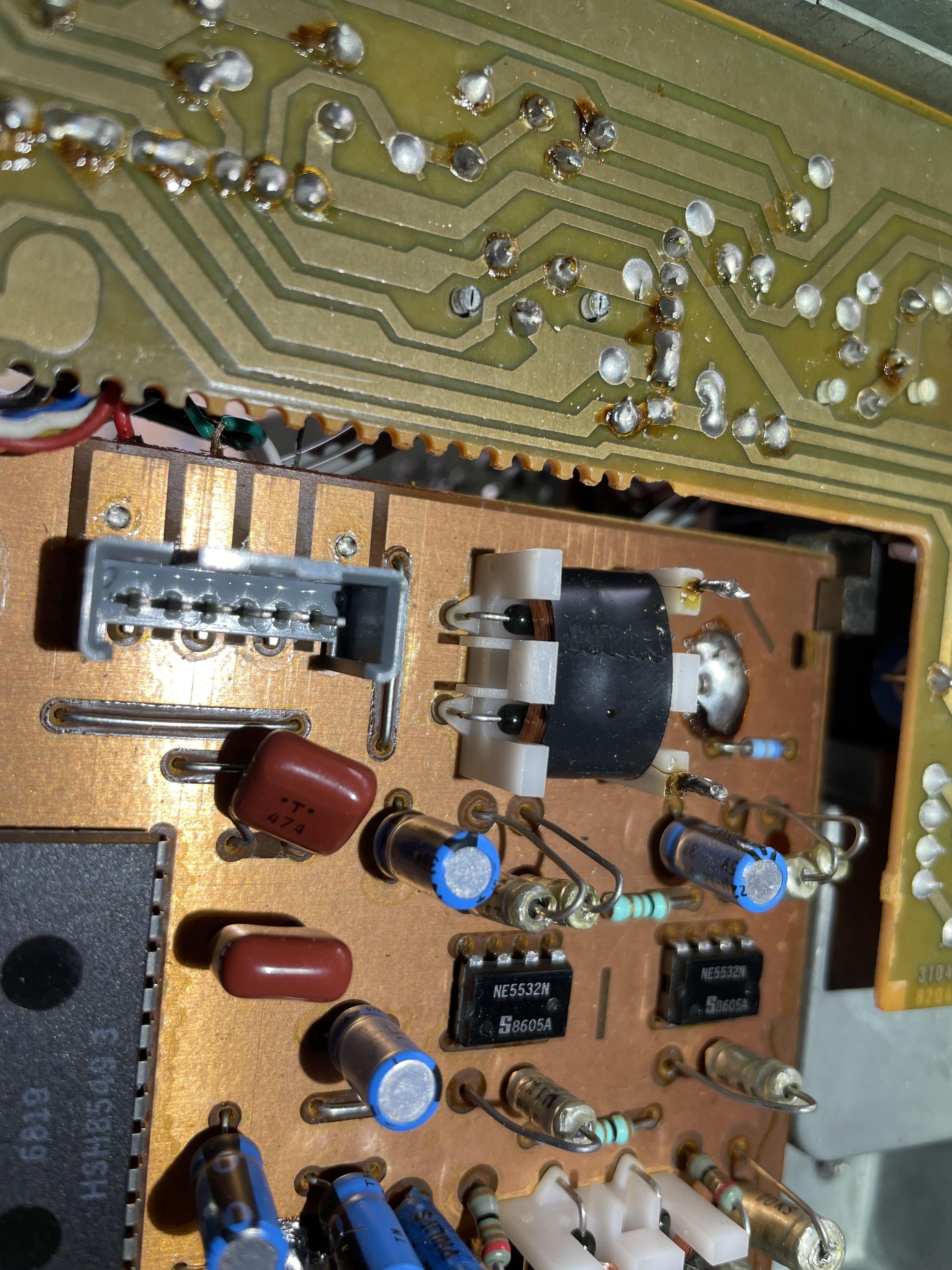
My question relates to the best method of replacing the reed switches in this relay

which I hope I am showing correctly in the attached image. Is it best to remove the relay in order to get to these, or can they be unsoldered with the relay in situ? I have purchased some RS FormA reedswiches, 0.5A, 140v which I hope will do the job (they look like they should fit in the confined space available). Also, is there any way of testing the reedswitches before replacing?while I’ve got it in pieces once more, I could redo all the griplets again but feed wire pins through the board this time, if it’s considered worthwhile….but I’m concerned about introducing any new faults or inadvertent damage.
Could the open circuit phono lead have caused any faults on the right channel amp circuit? My knowledge of electronics is more from the valve era, and even that is somewhat sketchy these days! However, I have managed to refurbish a Beomaster 900K and 2200 (adding Bluetooth modules to both) and a currently using a Beomaster 2300 along with an Arylic wireless streaming preamp (no room for any extra modules inside the 2300 that I could see!)
thanks in advance, and hope someone can help me get this CD player fully functioning again.
Ken
17 April 2022 at 02:29 #34225Those relays are not likely your problem as they only govern pre-emphasis and end up simply bypassing a resister. Your best bet is to try and trace a test tone from a CD. If you don’t have a scope an AC multimeter can work if your tone is a bass one.
17 April 2022 at 04:29 #34227Many thanks for the quick responses. And thanks Martin for the reed switch replacement advice – right channel reed element promptly replaced and all is working well now on both channels. An excellent sounds, on the brief test I’ve carried out so far.
Glad I didn’t have to delve any further into the electronics – I do have a scope (but it’s at our property in the USA…)…however, I have yet to work out how to use it, though I have several vintage radio sets there that might require it’s use some day!thanks again,
Ken
17 April 2022 at 07:22 #34226The reed elements closest to the end of the board are indeed mute switches, and they
are known to fail. I have replaced many.
Cut them at the bend, pull them out, insert new and solder to the stubs of the old.Martin
- AuthorPosts
- You must be logged in to reply to this topic.


