- This topic has 15 replies, 4 voices, and was last updated 2 years, 4 months ago by
Rullebör.
- AuthorPosts
- 22 September 2022 at 05:18 #39155
Hi all,
I hope to get some input on a repair of the amp of a Beolab Penta 2 (6621). Bought them recently and seller said one amp ran hot and went into protection mode.
I recapped with the hopes of resolving the issue, the amp now turns on alright with green light but soon runs very hot and bias won’t adjust below ca 500mV. I have measured the surrounding transistors in circuit and the voltages seem reasonable.
Any ideas what this could be or what to check next? Thankful for any input, haven’t worked on b&o amps before.
22 September 2022 at 08:22 #39156Did you replace the trim pots?
22 September 2022 at 09:03 #39157Yes, using the ones from the beoparts package. R59 adjusts offset just fine but R95 can’t get the bias down to the 30 mv range. Setting R95 at anything but minimum activates protection circuit and orange light.
23 September 2022 at 01:57 #39158I’m certainly not an “expert” on these amps, but I’ll try to help by asking some general questions. At the very least, there will be a bit more information here in case someone with in-depth knowledge of the common Penta amps failure modes chimes in.
Are any of the main transistors or load resistors discolored?
What are the actual voltages on the +68v and -68v power supplies?
Did you replace the power supply capacitors?
Have you reflowed the solder on the board connectors? Or at least carefully checked for cold solder joints?
It also might be helpful if you could upload some pictures of the component and trace sides of the circuit boards.
Glitch
24 September 2022 at 08:59 #39159Thanks, really appreciate it!
Yes I replaced the psu capacitors. Problem is now amp is going into protect mode again, too fast to get a measurement on the +/-68V.
Transistors look fine to me but will check more closely.
I have not reflowed the points of board connectors since I left them in, should that be done?
I found a lifted trace at the ground wire that might have lifted more now, trying to fix it with wiring. So that’s the weird thing in the middle of the picture of the trace side of the board.
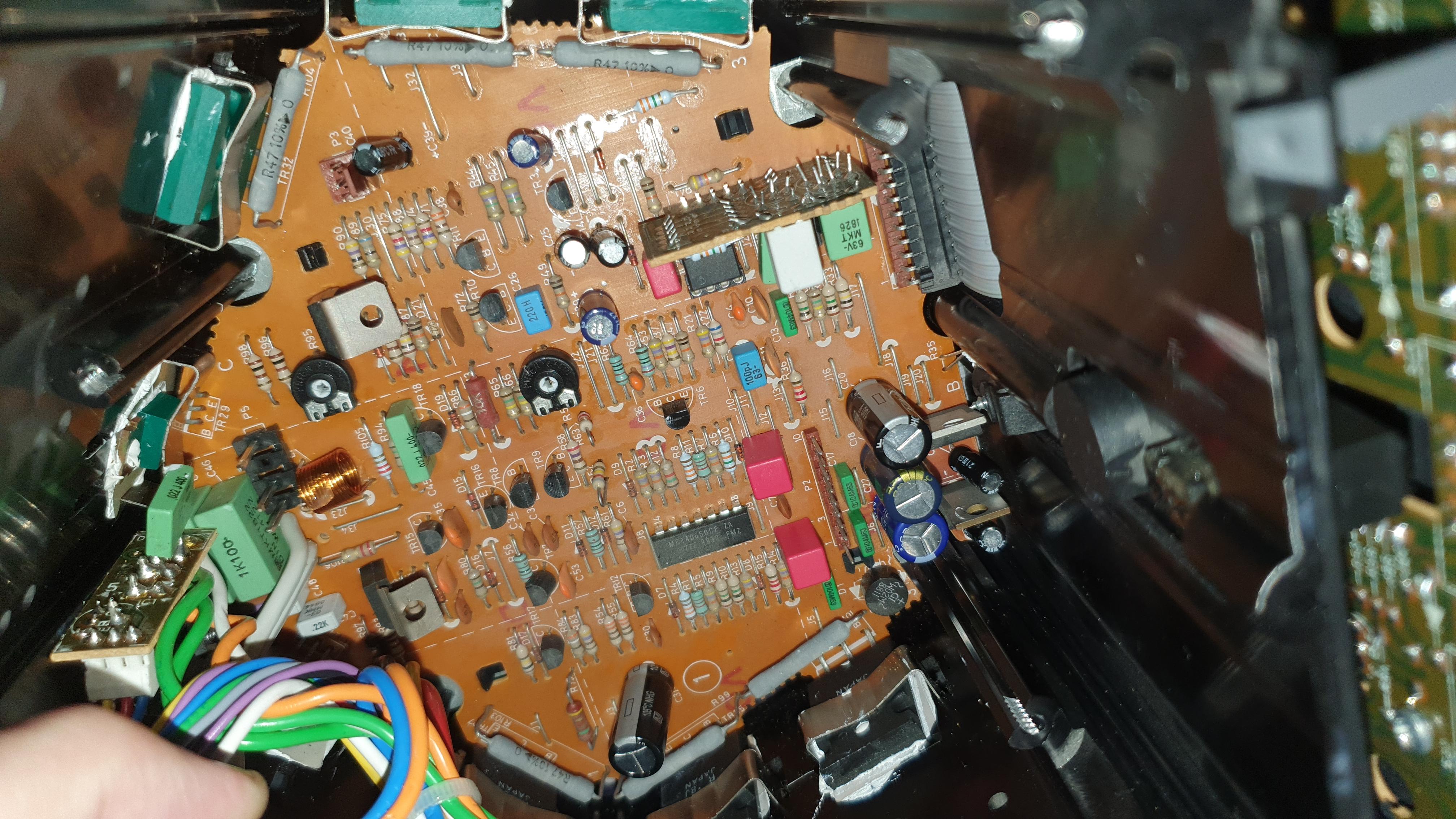
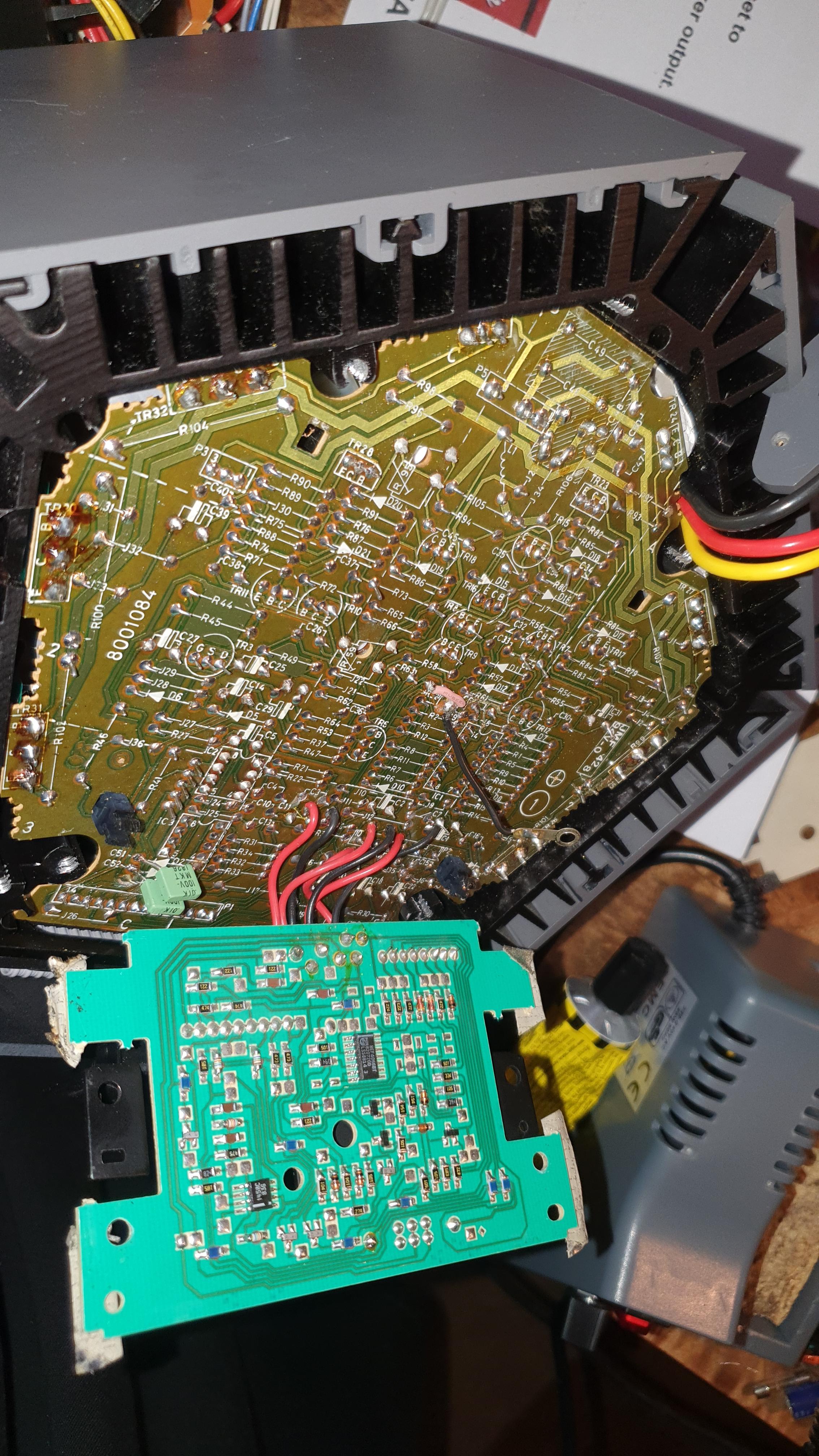 24 September 2022 at 09:56 #39160
The transistors and load resistors “look” similar to my working Penta2’s (i.e. no obvious overheating). I wouldn’t mess with them right now.
Probably not the problem, but are you sure you have the trim 100 and 220 trim pots in the correct location?
While you are double checking… check the polarity of the power supply capacitors. I recall that the markings on the original capacitors could be misinterpreted.
The soldering on some of the transistors doesn’t look like I would expect coming from the factory. I would clean-up the flux residue and do a closer inspection. It might be just the camera angle, but the solder from TR32 seems close to the trace.
I would carefully inspect the board connections even if you didn’t touch the connectors. I use either a 7X loupe and a bright light or take a picture with a macro lens and zoom in on the pictures on the computer screen. Even if I don’t find any obvious issues, I usually reflow solder on the board connectors as a precautionary measure.
I had trouble setting the bias on one of my other B&O amps. It turned out to be a bad ground connection to the preamp. The symptoms were similar to what you described where the full range of adjustment on the trim pot wouldn’t get the bias to a proper value.
I am also interested in hearing from others the possible causes for the amp running hot.
Glitch
24 September 2022 at 10:05 #39161For reference, the crack at pin 7 is the kind of thing to look for. The “stress rings” around the other pins look like they are getting close to failing.
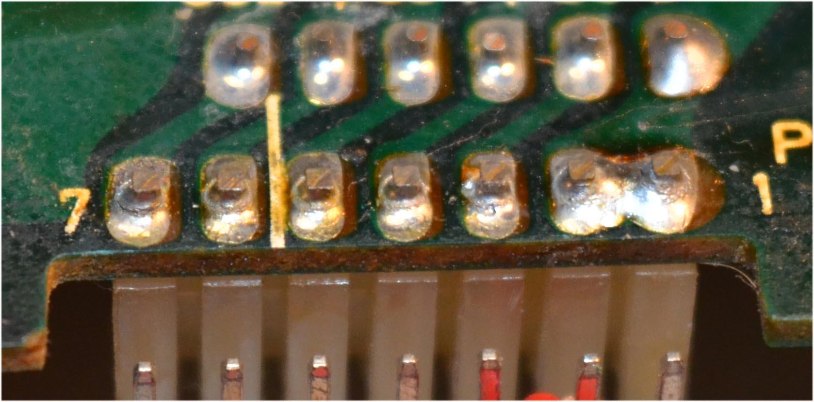
Glitch
25 September 2022 at 01:35 #39164You can’t do ohm readings on a powered circuit.
Martin
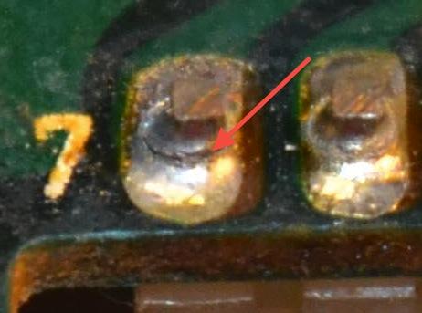
25 September 2022 at 05:17 #39165slanbexx wrote: Afraid I have a hard time making out the crack on pin 7 in the picIt’s the dark “smiley”:
 Glitch wrote: It might be just the camera angle, but the solder from TR32 seems close to the trace.
Also maybe camera, but TR31 “E” and “C” look like there might be a short in that labyrinth of solder dots. (Can’t be, given the symptom you describe, but still worth a check.)
25 September 2022 at 07:13 #39162My first thought was also, if you had the trimmers mixed up when you fitted them.
Martin
25 September 2022 at 08:32 #39163I also thought so but checked the ohm with dmm in circuit and it’s correct. One thing that puzzled me was that while turned the 220 trimresistor would read above 220 ohm and after turning off would steadily decline down to the ~110ohm it was set to. Something to do with how the circuit design or indicative of a fault?
Thanks for the guidance, I’ll go over the board once more and inspect the joints more carefully. Afraid I have a hard time making out the crack on pin 7 in the pic but gives me an idea of what to look for.
28 September 2022 at 02:42 #39167Thanks for letting us know that you got the amp working.
I’m glad you didn’t have to resort to the Beovox option. IMHO, the BeovoxPentas just don’t “look right” once you are used to the BeolabPentas.
Finding a good condition, intact display cover will be a challenge. I had the same problem and ended up with an alternative solution.
Glitch
28 September 2022 at 10:59 #39166My dudes, thanks to everyone for your guidance! The amp is up and running with well-adjusted bias and offset.
After both reflowing the suspicious looking transistor joints and replacing the lifted ground trace everything seems to work just fine. Hard to tell if it was the ground trace already making troubles before I started working on the amp or if it was the transitors soldered. Since they had obviously been serviced before and the soldering suggests work on the transistors both issues could have arisen through sloppy soldering.
Happy to save these from becoming beovoxes : )
Now I just need to find an intact yellow display cover…
10 October 2022 at 04:35 #39169I decided to take the “restomod” path with my Pentas since they were a bit rough when I bought them used. The yellow covers were cracked and glued back together several times and looked pretty bad. The grill fabric was also in need of replacement. The bases had their share of scuffs and scratches. I ended up repainting all of the gray and mirrored parts. I went through two iterations with the display covers.
The first iteration was fill in the cracks and paint the covers. Of course, I lost the use of the displays. This is a feature that I really didn’t “need” and I haven’t missed having it.
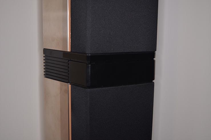
The second iteration was to make a 3D printed part that matched the grooved trim piece. This actually matches much better than the picture makes it look (flash problem?).
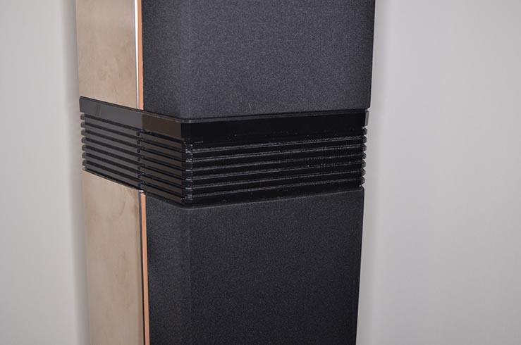
I also experimented with designs with a painted cover with a cutout for the original display. I also tried fitting a replacement color TFT display in place of the original display. In the end, we (by “we”, I mean my wife) decided that the speakers fit our decor better without the displays.
Glitch
10 October 2022 at 09:41 #39170Impressive work, it really does look better! Maybe I’ll try something similar in the future if I can’t find covers.
10 October 2022 at 10:21 #39168Gotta ask, what is the alternative solution? Been trying to locate them online and through B&O with no luck…
- AuthorPosts
- You must be logged in to reply to this topic.


