- This topic has 9 replies, 2 voices, and was last updated 1 year, 7 months ago by
Madskp.
- AuthorPosts
- 6 June 2023 at 01:54 #47025
I have acquired a used Beolab 3500 MKII. As described in this thread https://beoworld.dev.idslogic.net/forums/topic/bl3500-and-the-mcl-pl-connector/page/3/#post-20934 I have some issues with Masterlink on it so opening this separate thread as a fault finding / repair thread.
As mentioned in the other thread it does respond to options settings commands from the remote, and to the service commands like Menu, Menu, 0, 2, GO
Also able to play sound through the PL connector when using Menu, Menu, 0, 4, GO
It will however not respond to any source commands, and when connected to ML
I get an error 1, 2 or 4 when Pressing Menu, menu, 0, 2, GO
I have tried replaced the IR board with one from a MK1 BL3500, but nothing changed.
Also replaced the microcomputer board with the on from the MKI BL3500, keeping the MKII IR board. Still errors.
If I replace both the microcomputer and the IR board with those from the MKI BL 3500 it works fine, so I think I can rule out the crossfield and plug board.
I have also tried to install the IR and the microcomputer board from the MKII into the MKI BL 3500 and ended up with the same errors.
So there is probably both faults in the IR and the Microcomputer board.
Any ideas what I should look after here?
The easy thing would be to replace the boards, but the few I can find on Ebay cost more than I gave for the speaker, so I would rather try to see if it is repairable on component level
6 June 2023 at 02:49 #47026It’s a long shot but the behaviour would be similar if the Beo4 was in permanent LINK mode with the BL3500 in non-LINK mode – I seem to remember that you can still change L.OPT settings but that is about all. Is there any change in behaviour if you put the BL3500 in L.OPT 4?
But given that you are getting error codes I think the problem is more complex.
6 June 2023 at 02:58 #47027You are right that it behaves like it is in opt. 4 or 0 for that matter
however it is currently in opt 6, and then there is the errors related to ML
6 June 2023 at 03:00 #47028Oops didnt read your reply correctly. Will try with L.opt 4 later and report back
6 June 2023 at 05:51 #47029A few observations:
- I can not change option settings when the BL3500 MKII. is not connected to ML. This is possible on the MKI
- When I have it connected to ML (BLC1611) and change the option setting to L.OPT 4 also the service commands can not be done with normal commands.
- Measuring voltage levels on the 20 pin connector on the IR board all seems normal except for -5V which I can only measure at -4.3V, so here might be something
6 June 2023 at 07:04 #47030Measuring voltage levels on the 20 pin connector on the IR board all seems normal except for -5V which I can only measure at -4.3V, so here might be something
Tried measuring the -5V on the MKI and it shows -4.5V and that is working.
Another thing I noticed on the MKII is that the timer light is always on. If i touch the timer button and switch it to “timer off “the light will go out, but then turn on again when the text disaper in the display.
17 June 2023 at 12:43 #47031The service manaul for the MKII states that in case of an error 4 on should check the cables and the signal path (amplifiers in the data transceiver circuit).
As the MKII service manual don’t have diagrams I am using those from the MKI servicemanual.
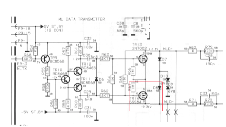
In that there is shown a transmitter and a reciever circiut for ML on the IR board. The transmitter part has some transistors where the reciever par has some IC’s. So I choose to focus on the transmitter part.

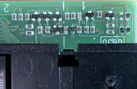
I tested all transistors and diodes and found that TR14 is not recognized by my component tester (so might be faulty) and D8 is short circiut.
Here is a picture of the placement (D8 is removed when I took the picture)

The placement of D8 is not the same as shown on the PCB layouts in the MKI service manual.
Now I will try to source these components and see if replacing them makes a difference.
Any insights as tho why the might have gone faulty are very welcome if I am overlooking something.
18 June 2023 at 06:02 #47032Now I will try to source these components and see if replacing them makes a difference.
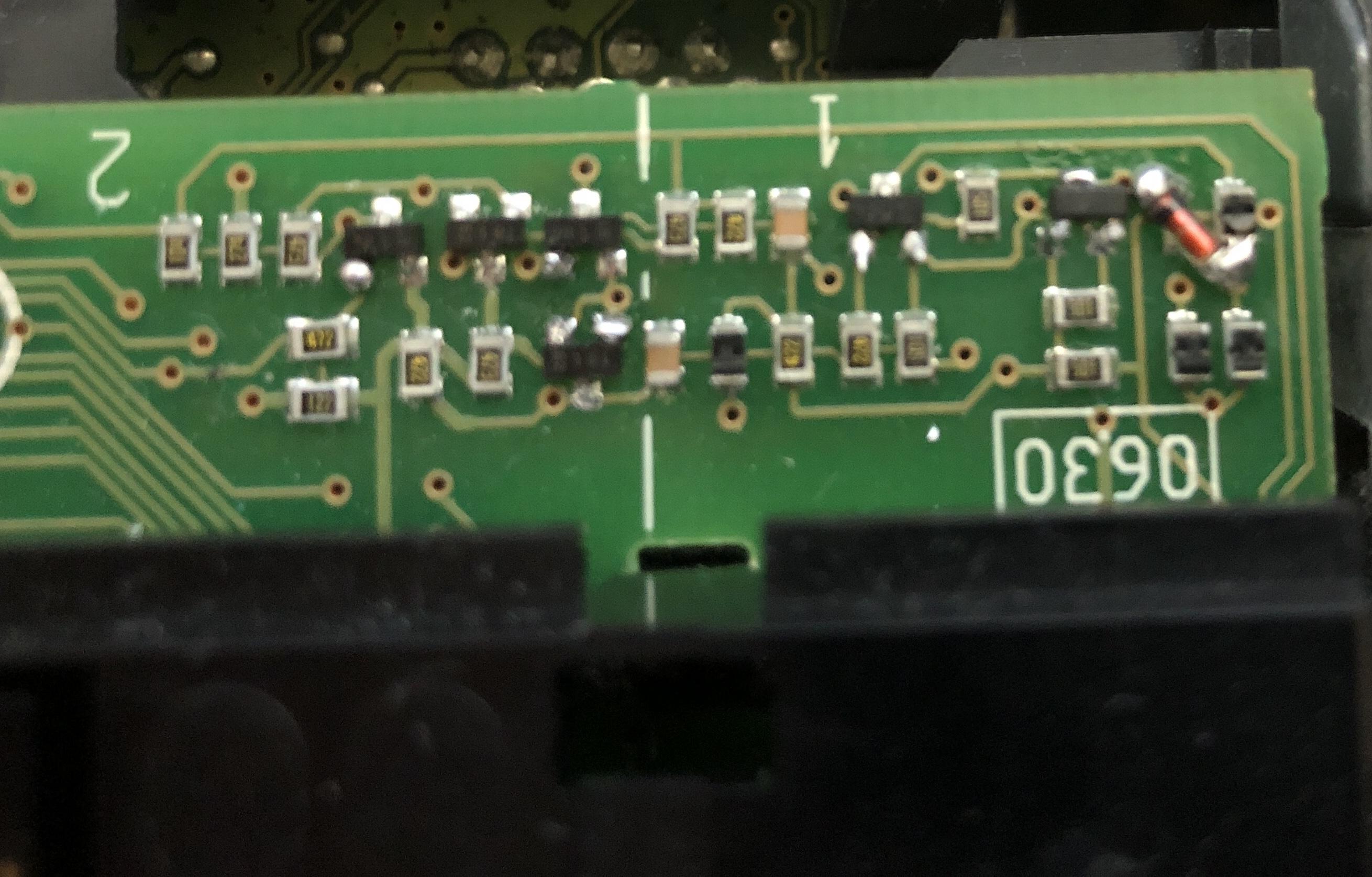
I found a replacement for TR14 in a faulty BLC 1615. Its an SMD part named BSS84. The marking on the part can aperently differ. The faulty one had the marking YBs, where as the other part and also the one in the MKI was marked SPs.
I found a matching diode to replace D8 on some scrap electronics. A little larger part but it could be mounted in an angled position.
The result is not pretty, but now ML is working again with no errors, and it responds to source commands when connected to a ML master.
 So now it’s back to the other thread for testing again.19 June 2023 at 01:22 #47034
Great result finding and fixing the ML fault
Yes that was nice that is was fixable.
Only downside is that now I have a faulty where I introduced a missing component making it even harder to diagnose 😉
19 June 2023 at 12:25 #47033Great result finding and fixing the ML fault – looking forward to seeing developments on the other thread!
- AuthorPosts
- You must be logged in to reply to this topic.


