- This topic has 5 replies, 2 voices, and was last updated 1 year, 4 months ago by
Guy.
- AuthorPosts
- 2 November 2023 at 07:33 #50071
Good evening, can anyone explain to me why the master control panel 5500 is unable to turn the Beo Gram 5500 turntable on and off? Thank you!
2 November 2023 at 07:47 #50072Hi and welcome to Beoworld!
I assume that the Beogram is connected to a Beomaster, because this will relay the remote commands.
If so, check that the DIN plug connecting the Beogram to the Beomaster has 7 pins. If pin 6 or 7 are missing then there will be no communication between devices and no remote control of the Beogram.
3 November 2023 at 08:52 #50073Hi Guy and thanks so much for your reply. In fact the beogram has a 6 pin cable. How can I replace it with a 7 pin one? Thank you!
3 November 2023 at 09:38 #50074Hi Guy and thanks so much for your reply. In fact the beogram has a 6 pin cable. How can I replace it with a 7 pin one? Thank you!
It’s strange to have just 6 pins. Normally pins 6 and 7 have been removed so that it can be connected to a non-B&O amplifier with a 5 pin DIN input.
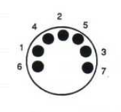
Pins 6 and 7 actually unscrew with a fine screwdriver, and your BG5500 just needs pin 6 for control data. The following diagram shows the pin diagram viewing the solder side of the plug (or looking into a socket). If possible, you may have to move pin 7 to 6.

You can buy replacement pins here: https://www.beoparts-shop.com/product/datalink-pin-for-remote-control-communications-din-cable/
If the above does not make sense, perhaps post a photo of the connector (showing the pins) so that we can advise further.
Also, what Beomaster are you using? BM5500?
3 November 2023 at 11:13 #50075Yes beomaster 5500 turntable beogram 5500 mcp 5500. Will it be easy to solder the wires? Isn’t there a possibility to directly replace the entire cable by dismantling the turntable? sorry for the ignorance and thanks for the quick replies
4 November 2023 at 11:26 #50076Isn’t there a possibility to directly replace the entire cable by dismantling the turntable?
I am not quite sure why you wish to replace the whole cable, rather than simply adding the correct connection. Perhaps the cable has been replaced in the past, and doesn’t have the correct core to carry the additional datalink signals.
Anyway, yes you could open up the turntable and replace the cable. The service manual would help with the dismantling and connections and is available on this site for Silver and Gold members.
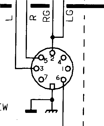
Here’s a sneak preview of the correct wiring of the cable (note that this is a mirror image of my earlier diagram – as if looking into the plug and viewing the pins). Pin 6 is datalink.

EDIT: The photo in this post may be useful – you can see the cable entering top right and routed to the front and then left: https://beoworld.dev.idslogic.net/forums/topic/beogram-5500-scraping-sound-any-ideas/#post-7118
- AuthorPosts
- You must be logged in to reply to this topic.


